LiftMaster MGJ MGJ S-SERIES Manual - Page 9
Control Wiring, Mount Warning Notice
 |
View all LiftMaster MGJ manuals
Add to My Manuals
Save this manual to your list of manuals |
Page 9 highlights
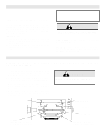
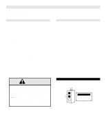
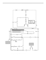
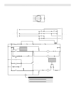
CONTROL WIRING DETERMINE WIRING TYPE Refer to the wiring diagram located on the inside cover the electrical box to determine the type of control wiring. MODEL MGJ SPECIAL CONTROL WIRING Standard C2 or B2 Wiring Model MGJ operators are shipped from the factory with jumper set for C2 wiring, which requires constant pressure on button to close the door. If momentary contact on close direction is desired (B2 wiring) you must include an entrapment protection device. See close control jumper setting below. Constant pressure on close (C2 wiring) Red jumper wire was placed on terminal #2 in the electrical enclosure. The operator will require constant pressure on close control in order to keep door moving in the close direction. Momentary contact on close (B2 wiring) Move red jumper wire from terminal #2 to terminal #3. The operator will require only momentary contact to close the door. If your operator was shipped from the factory with nonstandard control wiring or with optional accessories that require additional instructions, refer to the wiring diagram(s) indicated in the special control wiring data box. When a replacement wiring diagram is present, wiring diagrams in this manual will not apply. Refer only to the replacement wiring diagram for all connections. LOCATING THE CONTROL STATION All operators are supplied with some type of control station. Generally a three button station (OPEN/CLOSE/STOP) is provided. A two-position key switch or control station (OPEN/CLOSE) may be added or substituted when requested at the time of order. Mount the control station near the door. WARNING INSTALL THE CONTROL STATION WHERE THE DOOR IS VISIBLE, BUT AWAY FROM THE DOOR AND ITS HARDWARE. IF CONTROL STATION CANNOT BE INSTALLED WHERE DOOR IS VISIBLE, OR IF ANY DEVICE OTHER THAN THE CONTROL STATION IS USED TO ACTIVATE THE DOOR, A REVERSING EDGE MUST BE INSTALLED ON THE BOTTOM OF THE CAUTION DOOR. FAILURE TO INSTALL A REVERSING EDGE UNDER THESE CIRCUMSTANCES MAY RESULT IN SERIOUS INJURY OR DEATH TO PERSONS TRAPPED BENEATH THE DOOR. MOUNT WARNING NOTICE WARNING IMPORTANT: Mount WARNING NOTICE beside or below the push button station. Control Station OPEN Push CLOSE Buttons WARNING TO PREVENT ENTRAPMENT DO NOT START DOOR DOWNWARD WARNINGUNLESS DOORWAY IS CLEAR STOP WARNING Notice 9
-
 1
1 -
2
-
3
-
 4
4 -
 5
5 -
 6
6 -
 7
7 -
 8
8 -
 9
9 -
 10
10 -
 11
11 -
 12
12 -
 13
13 -
 14
14 -
15
-
16
 |
 |