LiftMaster MGJ MGJ S-SERIES Manual - Page 5
Operator Mounting,
 |
View all LiftMaster MGJ manuals
Add to My Manuals
Save this manual to your list of manuals |
Page 5 highlights
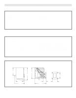
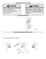
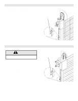
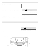
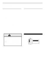
Remove the three cotter pins from the disconnect shaft. Do not discard the pins. Slide the disconnect shaft out of the support bracket. The release lever will now be free inside the motor frame. Remove the release lever and sash chain from the motor frame. Slide the disconnect hub, compression spring, and flatwasher from the end of the gear reducer shaft. Remove the disconnect support bracket by first removing the the two gear reducer housing screws. Replace the screws in the gear reducer and firmly tighten. 2. Re-assemble Disconnect Assembly Remove the two screws on the opposite side of the gear reducer and mount the disconnect support bracket with the notched side facing the motor. For the remainder of the installation, follow the steps outlined above in reverse order, referring to the illustration as necessary. OPERATOR MOUNTING Before your operator is installed, be sure the door has been properly aligned and is working smoothly. The operator may be wall mounted or mounted on a bracket or shelf. If necessary, refer to the operator preparations on page 3. Refer to the illustration and instructions below that suits your application. 1a. Wall Mounting The operator should generally be installed below the door shaft, and as close to the door as possible. The optimum distance between the door shaft and operator drive shaft is between 12" - 15". Refer to Figure 3. 1b. Bracket or Shelf Mounting The operator may be mounted either above or below the door shaft. The optimum distance between the door shaft and operator drive shaft is between 12" - 15". Refer to Figure 4. FIGURE 3 FIGURE 4 Typical Left Hand Wall Mounted Operator 1c. Place door sprocket on the door shaft. Do not insert the key at this time. 2. Wrap drive chain around door sprocket and join roller chain ends together with master link. 3. Raise operator to approximate mounting position and position chain over operator sprocket. 4. Raise or lower operator until the chain is slightly taut (not tight). Make sure the operator output shaft is parallel to door shaft and sprockets are aligned. When in position, secure the operator to wall or mounting bracket. 5. Align sprockets and secure, (see Figure 5). IMPORTANT: The shelf or bracket must provide adequate support, prevent play between operator and door shaft, and permit operator to be fastened securely and with the drive shaft parallel to the door shaft. FIGURE 5 Be sure door sprocket is properly aligned with drive before securing to the shaft. Chain Keeper 5
-
 1
1 -
 2
2 -
 3
3 -
 4
4 -
 5
5 -
 6
6 -
 7
7 -
 8
8 -
 9
9 -
 10
10 -
 11
11 -
12
-
13
-
14
-
15
-
16
 |
 |
