LiftMaster MGJ MGJ Manual
LiftMaster MGJ Manual
 |
View all LiftMaster MGJ manuals
Add to My Manuals
Save this manual to your list of manuals |
LiftMaster MGJ manual content summary:
- LiftMaster MGJ | MGJ Manual - Page 1
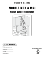
OWNER'S MANUAL MODELS MGH & MGJ MEDIUM DUTY DOOR OPERATOR 2 YEAR WARRANTY Serial # (located on electrical box cover) Installation Date Wiring Type www.liftmaster.com NOT FOR RESIDENTIAL USE 41B6 - LiftMaster MGJ | MGJ Manual - Page 2
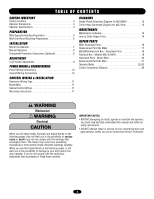
WARNING IMPORTANT NOTES: WARNING • BEFORE attempting to install, operate or maintain the operator, you must read and fully understand this manual and follow all WARNING safety instructions. • DO NOT attempt repair or service of your commercial door and gate operator unless you are an Authorized - LiftMaster MGJ | MGJ Manual - Page 3
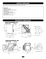
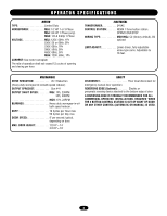
all components were provided. DESCRIPTION POWERHEAD ASSEMBLY OWNER'S MANUAL AND CAUTION LABELS HARDWARE BOX 3-BUTTON CONTROL STATION HOIST HAND CHAIN (MGH Model only) DOOR SPROCKET DOOR/OPERATOR DRIVE CHAIN OPERATOR DIMENSIONS WEIGHTS AND DIMENSIONS - MGJ HANGING WEIGHT: 50-60 LBS. 7.50" (19.05 - LiftMaster MGJ | MGJ Manual - Page 4
-oil-bath speed reducer) OUTPUT SPROCKET Size #41 OUTPUT SHAFT SPEED MGJ: 1Ph, 23RPM 3Ph, 39RPM MGH: 1Ph, 23RPM BEARINGS Heavy duty HP = 18' SAFETY DISCONNECT Floor level disconnect for emergency manual door operation. REVERSING EDGE (Optional Electric or pneumatic sensing device attached to - LiftMaster MGJ | MGJ Manual - Page 5
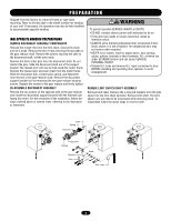
, the operators may also be field modified to accommodate opposite handing. MGJ OPPOSITE HANDING the pins. Slide the disconnect shaft out of the support AVERTISSEMENT bracket. The release lever will now be free inside : • DO NOT connect electric power until instructed to do so. • If the door lock - LiftMaster MGJ | MGJ Manual - Page 6
; or if the operator is being mounted in a horizontal position. HAND CHAIN RIGHT/LEFT CONVERSION 1. Remove snap ring from end of shaft on the hoist side. 2. Remove the washers, chain guide and chain wheel. 3. Remove drive pin from shaft and relocate to the opposite side. 4. Install chain wheel - LiftMaster MGJ | MGJ Manual - Page 7
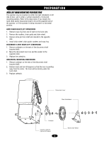
instructions below that suits your application. FIGURE 1 MOUNT THE OPERATOR 1. Wall Mount: The operator adequate support, prevent play between operator and door shaft, and permit operator to be pass it through both openings in the chain guide. Remove enough links so chain hangs approximately 2' - LiftMaster MGJ | MGJ Manual - Page 8
the operator BEFORE manually operating your door. MGJ 2. The door may now be pushed up or pulled down manually or if equipped with manual hand door manufacturer, mount the sensing edge on the door according to the instructions provided with the edge. The sensing edge may be electrically connected - LiftMaster MGJ | MGJ Manual - Page 9
as door fully seats at the floor. WARNING To avoid SERIOUS PERSONAL INJURY or DEATH from electrocution, disconnect electric power BEFORE manually moving limit nuts. AVERTISSEMENT ATTENTION CLOSE Limit Switch AVERTISSEMENT OPEN Limit Switch AVERTISSEMENT Actuator SAFETY (Aux. Close) Limit Switch - LiftMaster MGJ | MGJ Manual - Page 10
and secured, at that time the unit may be returned to service. • Disconnect power at the fuse box BEFORE proceeding. Operator MUST be properly grounded and connected in accordance with local electrical codes. The operator should be on a separate fused line of adequate capacity. • ALL electrical - LiftMaster MGJ | MGJ Manual - Page 11
missing, or you are unsure of the wiring type for your operator, contact the customer service department @ 1-800-528-2806. WARNING TO PREVENT ENTRAPMENT DO NOT START DOOR DOWNWARD UNLESS DOORWAY IS CLEAR MOUNTING INSTRUCTIONS All operators are supplied with some type of control station. Generally - LiftMaster MGJ | MGJ Manual - Page 12
SINGLE PHASE SCHEMATIC DIAGRAM FOR MGJ/MGH L2 BK BK CLOSE-B BL Y C N.O. W RES. OPEN-A R Y CAPACITOR R MOTOR * O/L BK L1 BR WIRE NUT PR1. 3 STOP 4 Y (WHEN PRESENT) MOVE JUMPER WIRE TO TERMINAL #2 FOR - LiftMaster MGJ | MGJ Manual - Page 13
THREE PHASE SCHEMATIC DIAGRAM FOR MGJ ONLY 230V BRAKE (WHEN PRESENT) 230V BRAKE (WHEN PRESENT) BRN GY PUR YEL BRN BL/BK 1 74 2 8 5 O/L* 3 96 BL/BK BRN GY PUR YEL BRN - LiftMaster MGJ | MGJ Manual - Page 14
required Manual Disconnect Check & Operate WARNING SERVICING, ALWAYS DISCONNECTAOPVEREARTOTRIFSROSMEPMOWEERNSTUPPLY. HOW TO ORDER REPAIR PARTS OUR LARGE SERVICE ORGANIZATION SPANS AMERICA Installation and service information are available. Call our TOLL FREE number: 1-800-528-2806 www.liftmaster - LiftMaster MGJ | MGJ Manual - Page 15
THIS PAGE INTENTIONALLY LEFT BLANK - LiftMaster MGJ | MGJ Manual - Page 16
MGH ILLUSTRATED PARTS 11 1 4 2 K2 (K72-12789) 9 5 3 6 7 8 K1 (K75-12783) 10 K3 (K75-12829) 16 - LiftMaster MGJ | MGJ Manual - Page 17
lists below for replacement kits available for your operator. If optional modifications and/or accessories are included with your operator, certain components may be added or removed from these lists. SERVICE KITS Item Part # K1 K75-12783 K2 K72-12789 K3 K75-12829 Description Disconnect assembly - LiftMaster MGJ | MGJ Manual - Page 18
MGJ/MGH ELECTRICAL BOX - ILLUSTRATED PARTS 3 K1 (K75-12567) 1 9 5 7 9 1 3 8 6 2 4 18 - LiftMaster MGJ | MGJ Manual - Page 19
ELECTRICAL BOX- MODELS MGJ & MGH For replacement of electrical box, motor or brake components be sure to match model number of your unit to kit number below to ensure proper voltage requirements. SERVICE KITS ITEM PART # DESCRIPTION K1 K72-12565 Limit shaft assembly Complete with: Limit shaft, - LiftMaster MGJ | MGJ Manual - Page 20
2 3 5 K1 K75-12567 ILLUSTRATED PARTS - MODEL MGJ 20 4 1 - LiftMaster MGJ | MGJ Manual - Page 21
are included with your operator, certain components may be added or removed from these lists. ITEM K1 PART # K75-12567 SERVICE KITS DESCRIPTION Disconnect assembly kit Complete with: Disconnect hub, bevel gear yoke, disconnect shaft, release lever, disconnect support bracket, sprocket 41B19 - LiftMaster MGJ | MGJ Manual - Page 22
OPERATOR NOTES 22 - LiftMaster MGJ | MGJ Manual - Page 23
OPERATOR NOTES 23 - LiftMaster MGJ | MGJ Manual - Page 24
When adding accessories, install them one at a time and test each one after it is added to ensure proper installation and operation with the Commercial Door Operator. 4. Auxiliary control equipment may be any normally open two wire device such as pull switch, single button, loop detector, card key
-
 1
1 -
 2
2 -
 3
3 -
 4
4 -
 5
5 -
 6
6 -
 7
7 -
8
-
9
-
10
-
11
-
12
-
13
-
14
-
15
-
16
-
17
-
18
-
19
-
20
-
21
-
22
-
23
-
24
 |
 |

O W N E R ’ S
M A N U A L
MODELS MGH & MGJ
MEDIUM DUTY DOOR OPERATOR
NOT FOR RESIDENTIAL USE
41B6
Serial #
(located on electrical box cover)
Installation Date
Wiring Type
www.liftmaster.com
2
YEAR
WARRANTY