LiftMaster MGJ MGJ Manual - Page 5
Preparation, MGJ Opposite Handing Preparations
 |
View all LiftMaster MGJ manuals
Add to My Manuals
Save this manual to your list of manuals |
Page 5 highlights
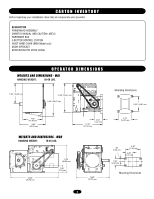
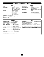
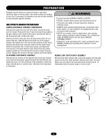
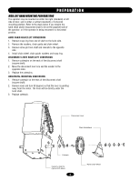
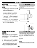
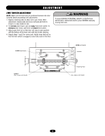
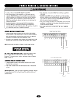
WARNING PREPARATION WARNING CAUTION Shipped from the factory for either left hand or right hand mounting. Refer to the last digit in the model number for handing of your unit. If necessary, the operators may also be field modified to accommodate opposite handing. MGJ OPPOSITE HANDING PREPARATIONS REMOVE DISCONNECT ASSEMBLY COMPONENTS Remove the master link from the limit chain, remove the chain and set it aside. Remove the two e-rings securing the sprocket on the gear reducer shaft. Remove the screws securing the yoke to the disconnect shaft, set the yoke aside. Remove the three cotter pins from the disconnect shaft. Do not discard the pins. Slide the disconnect shaft out of the support AVERTISSEMENT bracket. The release lever will now be free inside the motor frame. Remove the release lever and sash chain from the motor frame. Slide the disconnect hub, compression spring, and flatwasher ATTENTION from the end of the gear reducer shaft. Remove the disconnect support bracket by first removing the two gear reducer housing screws. Replace the screws in the gear reducer and firmly tighten. RE-ASSEMBLE DISCONNECT ASSEMBLY Remove the two screws on the opposite side of the gear reducer and mount the disconnect support bracket with the notched side facing the motor. For the remainder of the installation, follow the steps outlined above in reverse order, referring to the illustration as necessary. WARNING To prevent possible SERIOUS INJURY or DEATH: • DO NOT connect electric power until instructed to do so. • If the door lock needs to remain functional, install an interlock switch. • ALWAYS call a trained professional door serviceman if door binds, sticks or is out of balance. An unbalanced door may not reverse when required. • NEVER try to loosen, move or adjust doors, door springs, cables, pulleys, brackets or their hardware, ALL of which are under EXTREME tension and can cause SERIOUS PERSONAL INJURY. AVERTISSEMENT • Disable ALL locks and remove ALL ropes connected to door BEFORE installing and operating door operator to avoid entanglement. AVERTISSEMENT REMOVE LIMIT SWITCH SHAFT ASSEMBLY Remove limit chain. Remove the e-ring and washers from the side away from the limit chain sprocket. Remove limit shaft. The limit adjust nuts will need to be unscrewed while removing shaft. To reassemble follow the above steps in reverse order. ADVERTENCIA PRECAUCIÓN Keys Spring Disc Hub Sprocket E-Ring Bracket Yoke ADVERTENCIA Shaft ADVERTENCIA Disc Lever 5
-
 1
1 -
 2
2 -
 3
3 -
 4
4 -
 5
5 -
 6
6 -
 7
7 -
 8
8 -
 9
9 -
 10
10 -
 11
11 -
12
-
13
-
14
-
15
-
16
-
17
-
18
-
19
-
20
-
21
-
22
-
23
-
24
 |
 |
