LiftMaster MGJ MGJ Manual - Page 11
Control Wiring & Installation, Determine Wiring Type, Special Control Wiring, Mounting Instructions
 |
View all LiftMaster MGJ manuals
Add to My Manuals
Save this manual to your list of manuals |
Page 11 highlights
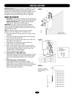
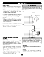
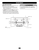
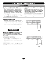
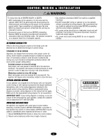
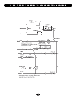
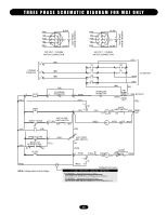
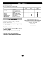
NG C O N T R O L W I R IWNAG R&NIINNGS T A L L A T I O N N WARNING To reduce the risk of SEVERE INJURY or DEATH: • ANY maintenance to the operator or in the area near the operator MUST NOT be performed until disconnecting the electrical power and locking-out the power via the operator power switch. Upon completion of maintenance the area MUST be cleared and secured, at that time the unit may be returned to service. • Disconnect power at the fuse box BEFORE proceeding. Operator MUST be properly grounded and connected in accordance with local electrical codes. The operator should be on a separate fused line of adequate capacity. • ALL electrical connections MUST be made by a qualified individual. • DO NOT install ANY wiring or attempt to run the operator without consulting the wiring diagram. We recommend that you install an optional reversing edge BEFORE proceeding with the control station installation. • ALL power wiring should be on a dedicated circuit and well protected. The location of the power disconnect should be visible and clearly labeled. • ALL power and control wiring MUST be run in separate conduit. EMENDETTERMINE WIRING TYPE AVERTISSEMENT ON Refer to the wiring diagram located on the inside cover the AVERTISSEMENT electrical box to determine the type of control wiring. STANDARD C2 OR B2 WIRING Operators are shipped from the factory with jumper set for C2 wiring, which requires constant pressure on button to close the door. If momentary contact in close direction is desired (B2 wiring) you must include an entrapment protection device. See close control jumper setting below. Constant pressure on close (C2 wiring) Red jumper wire was placed on terminal #2 in the electrical enclosure. The operator will require constant pressure on close control in order to keep door moving in the close direction. Momentary contact on close (B2 wiring) Move red jumper wire from terminal #2 to terminal #3. The operator will require only momentary contact to close the door. SPECIAL CONTROL WIRING If your operator was shipped from the factory with non-standard control wiring or with optional accessories that require additional ENCIAinstructions, refer to the wiring diagram(s) indicated in tAhe DVERTENCIA special control wiring data box. When a replacement wiring diagram is present, wiring diagrams in this manual will not apply. IÓN ADVERTENCIA Refer only to the replacement wiring diagram for all connections. IMPORTANT NOTE: If your wiring diagram is missing, or you are unsure of the wiring type for your operator, contact the customer service department @ 1-800-528-2806. WARNING TO PREVENT ENTRAPMENT DO NOT START DOOR DOWNWARD UNLESS DOORWAY IS CLEAR MOUNTING INSTRUCTIONS All operators are supplied with some type of control station. Generally a 3-button station (OPEN/CLOSE/STOP) is provided. A two-position key switch or control station (OPEN/CLOSE) may be added or substituted when requested at the time of order. 1. Mount WARNING NOTICE beside or below the control station. 2. Mount control station(s) within line of sight of door(s). Control Station 4' Approximate 11
-
 1
1 -
2
-
3
-
4
-
5
-
 6
6 -
 7
7 -
 8
8 -
 9
9 -
 10
10 -
 11
11 -
 12
12 -
 13
13 -
 14
14 -
 15
15 -
 16
16 -
17
-
18
-
19
-
20
-
21
-
22
-
23
-
24
 |
 |