LiftMaster RSL12U RSL12U Installation Manual - Page 37
Appendix, Dual Gate Settings
 |
View all LiftMaster RSL12U manuals
Add to My Manuals
Save this manual to your list of manuals |
Page 37 highlights
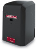
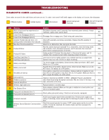
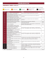
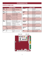
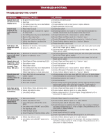
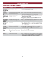
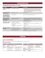
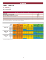
TROUBLESHOOTING TROUBLESHOOTING CHART continued... SYMPTOM Solenoid lock not working correctly. POSSIBLE CAUSES a) Solenoid wired incorrectly Switched (SW) Accessory power remaining on. a) In limit setup mode Accessories connected to a) Normal behavior Switch (SW) Accessory power not working correctly, turning off, or resetting. Accessories connected to Accessory power not working correctly, turning off, or resetting. a) Accessory power protector active b) Defective control board Solar operator not getting enough cycles per day a) Insufficient panel wattage b) Excessive accessory power draw c) Old batteries d) Solar panels are not getting enough sunlight Solar operator, insufficient standby time a) Insufficient panel wattage b) Excessive accessory power draw c) Battery capacity too low SOLUTIONS a) Check that Solenoid is wired to N.O. and COM terminals. Check that Solenoid has power (do not power solenoid from control board accessory power terminals). If shorting lock's NC and COM wires does not activate Solenoid, then replace Solenoid lock or Solenoid wiring (refer to Wiring Diagrams). a) Learn the limits a) Move accessory to accessory power "ON" a) Disconnect all accessory powered devices and measure accessory power voltage (should be 11.5 - 17.5 Vdc). If voltage is correct, connect accessories one at a time, measuring accessory voltage after every new connection. b) Replace defective control board a) Add more solar panels b) Reduce the accessory power draw by using LiftMaster low power accessories c) Replace batteries d) Relocate the solar panels away from obstructions (trees, buildings, etc.) a) Add more solar panels b) Reduce the accessory power draw by using LiftMaster low power accessories c) Use batteries with higher amp hour (AH) rating APPENDIX DUAL GATE SETTINGS NOTE: We recommend that all accessories and board configurations are set on the primary operator. MAIN CONTROL BOARD FEATURE Timer-toClose Bi-Part Delay Switch PRIMARY OPERATOR Set the TTC dial to desired setting Bi-Part Delay: ON (will open last and close first) Tandem Mode: OFF Synchronized Close: ON SECONDARY OPERATOR OFF Bi-Part Delay: OFF (will open first and close last) Tandem Mode: OFF Synchronized Close: ON ACCESSORY PRIMARY OPERATOR Remote Controls Program remote controls 1 to 50 to the primary operator. LiftMaster Program to primary Internet Gateway operator. Garage and Gate Program to primary Monitor operator. SECONDARY OPERATOR Program remote controls 51 to 100 to the secondary operator 36
-
 1
1 -
2
-
3
-
4
-
5
-
6
-
7
-
8
-
9
-
10
-
11
-
12
-
13
-
14
-
15
-
16
-
17
-
18
-
19
-
20
-
21
-
22
-
23
-
24
-
25
-
26
-
27
-
28
-
29
-
30
-
31
-
 32
32 -
 33
33 -
 34
34 -
 35
35 -
 36
36 -
 37
37 -
 38
38 -
 39
39 -
 40
40 -
 41
41 -
 42
42 -
43
-
44
-
45
-
46
-
47
-
48
 |
 |