LiftMaster RSL12U RSL12U Installation Manual - Page 43
WIRING DIAGRAM, To protect against fire and electrocution
 |
View all LiftMaster RSL12U manuals
Add to My Manuals
Save this manual to your list of manuals |
Page 43 highlights
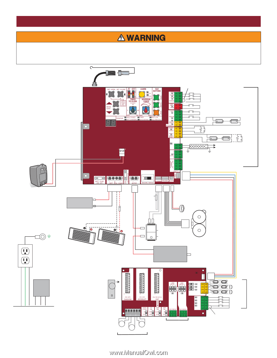
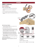
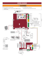
WIRING DIAGRAM Field Wiring Edge Edge To protect against fire and electrocution: • DISCONNECT power (AC or solar and battery) BEFORE installing or servicing operator. For continued protection against fire: • Replace ONLY with fuse of same type and rating. Antenna Coaxial Antenna Cable DIAGNOSTICS CONTROL BOARD Jumper Wire + + + N.C Photoelectric Sensors Photoelectric Sensors Black Red To J25 J25 AC & BATT FAIL BACKDRIVE COM LINK BA Shielded Twisted Pair Cable Primary/Secondary link to other gate operator Ground the shield of the cable to the chassis ground of each operator. Yellow Blue Black Red Transformer Red 12V 7AH Battery Black Red Black Product ID Blocking Diode Red Black White White Piezo Alarm Black Red N GND L L N GND White Green Black Accessory Power Outlets Heater Input Power Connection To Pin 2 To Pin 1 - + - + To Pin 6 To Pin 5 Run Stop/Reset One, two, or three 10W Solar Panels wired in parallel (30W maximum) Red Reset Switch 1/8 HP 12 Vdc Motor EXPANSION BOARD (Optional) APS Encoder Loop Detector OPEN CLOSE POWER 1 EYE ONLY 2 EYE/ EDGE 3 EYE/ EDGE COM SBC OPN CLS STP COM TO MAIN BOARD EYE EDGE OR EYE EDGE OR EYE N.C. SHADOW INTERUPT EXIT Jumper Wire Wire Loop Wire Loop Wire Loop Field Wiring 42 Field Wiring Field Wiring
-
 1
1 -
2
-
3
-
4
-
5
-
6
-
7
-
8
-
9
-
10
-
11
-
12
-
13
-
14
-
15
-
16
-
17
-
18
-
19
-
20
-
21
-
22
-
23
-
24
-
25
-
26
-
27
-
28
-
29
-
30
-
31
-
32
-
33
-
34
-
35
-
36
-
37
-
 38
38 -
 39
39 -
 40
40 -
 41
41 -
 42
42 -
 43
43 -
 44
44 -
 45
45 -
 46
46 -
 47
47 -
 48
48
 |
 |