LiftMaster SW470 SW490 GL BOARD Manual - Page 10
Pad Mounting (SW470), Parallel Mount, Perpendicular Mount,
 |
View all LiftMaster SW470 manuals
Add to My Manuals
Save this manual to your list of manuals |
Page 10 highlights
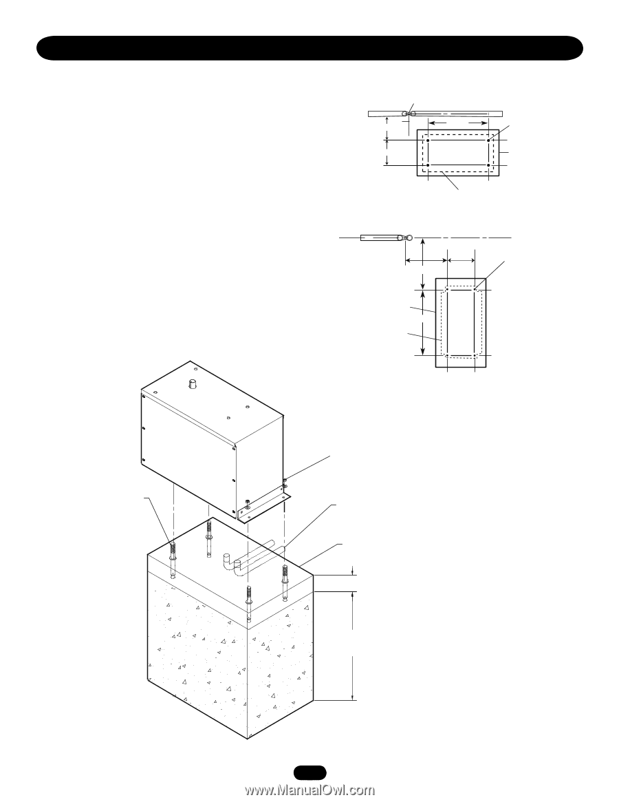
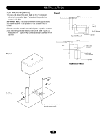
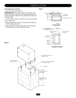
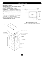
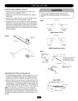
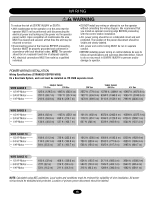
INSTALLATION PAD MOUNTING (SW470) 1. Layout the concrete pad (Figure 1). IMPORTANT NOTE: The relative location of the operator to the fence and the gate is critical. Be sure that the measurements for operator mounting are taken from the centerline of the fence and of the gate hinge. 2. Locate electrical conduit, as required, prior to pouring concrete. 3. Pour concrete pad. 4. Bolt the (2) pad mount brackets to the bottom of the operator with the hardware provided. 5. Secure the operator to the concrete pad. It is very important that the operator be level and square to the gate. Figure 1 Hinge Pin Fence c 9-3/4" 22-1/2" 24" 8" 1/2" Redhead (4 required.) Concrete pad 18"x34" min. Operator Parallel Mount Centerline Gate 6" 8" 18-3/4" 8"16"1/2" Redhead (4 required) Figure 2 Concrete pad 18"x34" min. 22-1/2" Profile of Operator SW470 Perpendicular Perpendicular Mount 1/2" red head bolts or anchors (4 required) Using suitable hardware secure operator to L-bolts Power and control wiring should be run in separate conduit Concrete Pad 2" to 4" above grade Depth required by local codes or below frost line 10
-
 1
1 -
2
-
3
-
4
-
 5
5 -
 6
6 -
 7
7 -
 8
8 -
 9
9 -
 10
10 -
 11
11 -
 12
12 -
 13
13 -
 14
14 -
 15
15 -
16
-
17
-
18
-
19
-
20
-
21
-
22
-
23
-
24
-
25
-
26
-
27
-
28
-
29
-
30
-
31
-
32
-
33
-
34
-
35
-
36
-
37
-
38
-
39
-
40
 |
 |