LiftMaster SW470 SW490 GL BOARD Manual - Page 18
Limit Switch Adjustment, LIMIT DIRECTION - motor
 |
View all LiftMaster SW470 manuals
Add to My Manuals
Save this manual to your list of manuals |
Page 18 highlights
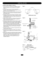
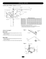
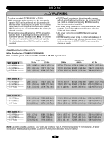
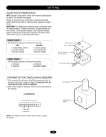
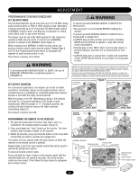
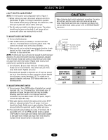
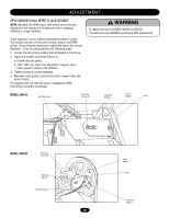
ADJUSTMENT WARNING LIMIT SWITCH ADJUSTMENT NOTE: For limit location and configuration refer to Figure 1. 1. Before turning on power, disconnect extension arm from gate bracket so gate is no longer connected to operator. Push manual release pin(s) up through the control arm, slide clevis pin in place and secure with a cotter pin. 2. The (3) collars are held to shaft by set screws. The collars should now be loose on the shaft. If not, loosen all set screws until collars are moving freely on shaft. CAUTION When following limit switch adjustment procedure, the motor belt will turn and the control arm will move during some steps. Keep hands and tools out of operator and away from arm and drive shaft unless power is off or SERIOUS INJURY may occur. TO ADJUST CLOSE LIMIT SWITCH 3. Turn on electrical power. 4. Press CLOSE button (if installed) or connect terminals 4 & 5 on J1 terminal strip to cause the gate to close. The control arm should move in the close direction. 5. When control arm is pointed in approximate direction of gate bracket (on fully closed gate) press STOP button or release terminals to stop control arm. NOTE: If control arm does not move far enough to point in proper direction, the close limit switch has been prematurely actuated. Turn off power, loosen set screw on close limit cam and rotate nut away from close limit switch. Repeat steps 3 and 4 until control arm is pointed in correct direction. 6. Turn off power. Be sure close limit cam is freely turning. Rotate cam in close direction. Stop when cam just clicks close limit switch. Tighten set screw. 7. Reconnect gate bracket to extension arm. If arm has moved too far in close direction to allow connection of gate bracket turn off power, connect terminals 5 & 7 to rotate arm in opposite direction, and press STOP button when arm is in desired position. TO ADJUST OPEN LIMIT SWITCH 8. Turn on power. Press OPEN button (if installed) or connect terminals 5 & 7 on J1 terminal strip. Gate should open. If gate does not open the open limit cam may be already actuating open limit switch or an improper electrical connection may have been made. Turn off power, inspect, correct and repeat this step. 9. When gate reaches desired fully open position press STOP button or release terminals. Turn off power. Limit cam should turn freely. Rotate cam in open direction. Stop when cam just clicks the open limit switch. Tighten set screw. 10. Fine tune both switch settings by using J1 terminals 4 & 5 (to CLOSE) of 5 & 7 (to OPEN) and the factory supplied STOP button to move gate and rotating limit collars slightly to alter gate travel. Rotate cam away from limit switch to increase travel, toward switch to decrease travel. Drive Shaft Limit Switch AVERTISSEMENT Set Screw Aux switch (optional) Limit Switch "A" Limit Switch "B" ATTENTION Limit Cam DIRECTION OF GATE TO OPEN RIGHT (Factory Default) LEFT LIMIT DIRECTION OPEN LIMIT A B CLOSE LIMIT B A ADVERTENCIA PRECAUCIÓN 18
-
 1
1 -
2
-
3
-
4
-
5
-
6
-
7
-
8
-
9
-
10
-
11
-
12
-
 13
13 -
 14
14 -
 15
15 -
 16
16 -
 17
17 -
 18
18 -
 19
19 -
 20
20 -
 21
21 -
 22
22 -
 23
23 -
24
-
25
-
26
-
27
-
28
-
29
-
30
-
31
-
32
-
33
-
34
-
35
-
36
-
37
-
38
-
39
-
40
 |
 |