Linksys NAS200 User Guide - Page 5
Product Overview, Front Panel, Back Panel - software
 |
UPC - 745883579150
View all Linksys NAS200 manuals
Add to My Manuals
Save this manual to your list of manuals |
Page 5 highlights
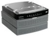
Chapter 1 Chapter 1: Product Overview Thank you for choosing the Linksys Network Storage System with 2 Bays. It features two SATA hard drive bays so you can add storage space to your network. There are also two USB ports that let you add USB hard drives for additional storage space, or you can connect a USB flash disk to access your portable files. (USB hard drives may require external power supplies.) WARNING: Do not block the air vents, and do not stack devices on top of the Network Storage System; otherwise, overheating can occur. (Air vents are located on the sides of the Network Storage System. Keep the area around the Network Storage System clear.) Front Panel Product Overview DISK 1 (Green) The DISK 1 LED serves two purposes. The LED is continuously lit when the hard drive in the top bay is ready for use. It flashes when the hard drive is reformatting or rebuilding with Disk 2 (RAID 1 mode). DISK 2 (Green) The DISK 2 LED serves two purposes. The LED is continuously lit when the hard drive in the bottom bay is ready for use. It flashes when the hard drive is reformatting or rebuilding with Disk 1 (RAID 1 mode). USB 1-2 (Green) The USB LED serves multiple purposes. The LED is continuously lit when the USB device is connected through the corresponding port. It flashes when the Network Storage System is accessing the USB device. After the LED powers off, the USB device can be removed. Back Up Button Press the Back Up button to initiate backup jobs specified by the backup software on your computer. (Your computer must be powered on for the jobs to run.) Back Panel POWER (Green/Orange) The POWER LED serves multiple purposes. It flashes green when the Network Storage System boots up, shuts down, prepares a disk, or scans a disk. The LED flashes green and orange when the Network Storage System upgrades its firmware. It is continuously lit green when the Network Storage System is ready for use. The LED is continuously lit orange when there is an error. (See "Appendix A: Troubleshooting" for more information.) ETHERNET (Green) The ETHERNET LED serves two purposes. The LED is continuously lit when a device is connected through the Ethernet port. It flashes to indicate network activity. DISK ACT (Green) The DISK ACT LED flashes when the Network Storage System is accessing data on the disk. DISK FULL (Green) The DISK FULL LED flashes when available disk capacity is less than 2% of total capacity or lower than the number you set through the web-based utility. Network Storage System with 2 Bays POWER Button Push the POWER button to power on or off the Network Storage System. POWER The POWER port connects to the included power adapter. ETHERNET The ETHERNET port connects to an Ethernet network device, such as a router or switch. USB 1 The USB 1 port connects to your USB storage device. Press the USB 1 button to eject the device from the USB 1 port. After the Network Storage System beeps once and the USB 1 LED powers off, you can remove the device. 1
-
 1
1 -
 2
2 -
 3
3 -
 4
4 -
 5
5 -
 6
6 -
 7
7 -
 8
8 -
 9
9 -
 10
10 -
 11
11 -
12
-
13
-
14
-
15
-
16
-
17
-
18
-
19
-
20
-
21
-
22
-
23
-
24
-
25
-
26
-
27
-
28
-
29
-
30
-
31
-
32
-
33
-
34
-
35
-
36
-
37
-
38
-
39
-
40
-
41
-
42
-
43
-
44
-
45
-
46
-
47
-
48
-
49
-
50
-
51
-
52
-
53
-
54
-
55
-
56
 |
 |
