Lowrance HDS-9 Gen2 Touch Installation Manual - Page 20
Power connection
 |
View all Lowrance HDS-9 Gen2 Touch manuals
Add to My Manuals
Save this manual to your list of manuals |
Page 20 highlights
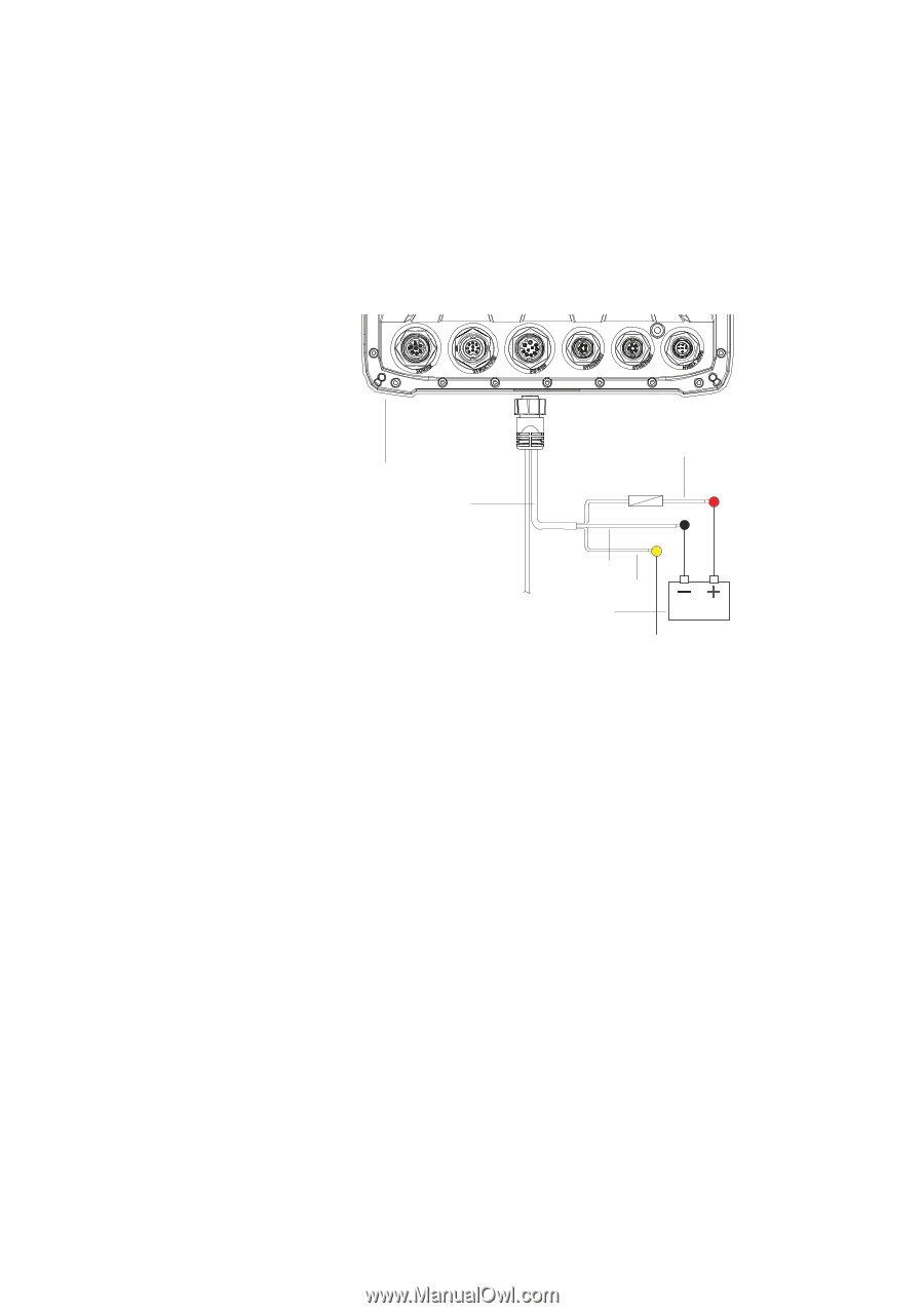
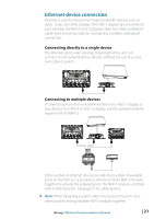
Power connection HDS Gen2 Touch displays are designed to be powered by a 12 V DC system. They are protected against reverse polarity, under voltage and over voltage. The plug of the supplied power cable has two discrete cables exiting from it. The thickest cable provides the following: • power into the system (Red and Black wires) • remote turn-on for certain Navico expansion modules (Yellow wire) 18 | 4 1 2 3 5 6 _+ 1 HDS display rear (9 & 12 connector arrangement shown) 2 Power cable 3 12 V negative wire (black) 4 12 V positive wire (red) shown with fuse holder fitted 5 Accessory Wake Up wire (yellow) 6 Vessel's 12 V DC supply Connect red to (+) DC using a 5 A fuse. Connect Black to (-) DC. Accessory wake up The yellow colored accessory wake up line may be used to control the power state of Navico modules such as SonicHub, StructureScan, and Broadband radar. This means that the modules are turned on the moment the display is powered up. ¼¼ Note: Broadband radar will be put in standby, when triggered by the accessory wake up line. For connection, simply combine all yellow wires on a common bus or to a single termination point. Wiring | HDS Gen2 Touch Installation Manual
-
 1
1 -
2
-
3
-
4
-
5
-
6
-
7
-
8
-
9
-
10
-
11
-
12
-
13
-
14
-
 15
15 -
 16
16 -
 17
17 -
 18
18 -
 19
19 -
 20
20 -
 21
21 -
 22
22 -
 23
23 -
 24
24 -
 25
25 -
26
-
27
-
28
-
29
-
30
-
31
-
32
-
33
-
34
-
35
-
36
-
37
-
38
-
39
-
40
 |
 |