MSI 945GCM5-F V2 User Guide - Page 13
Fan Power Connectors: CPUFAN1, SYSFAN1 - bios
 |
UPC - 816909039726
View all MSI 945GCM5-F V2 manuals
Add to My Manuals
Save this manual to your list of manuals |
Page 13 highlights
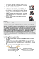
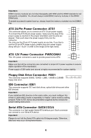
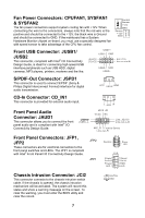
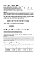
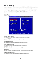
Fan Power Connectors: CPUFAN1, SYSFAN1 & SYSFAN2 The fan power connectors support system cooling fan with +12V. When connecting the wire to the connectors, always note that the red wire is the positive and should be connected to the +12V; the black wire is Ground and should be connected to GND. If the mainboard has a System Hardware Monitor chipset on-board, you must use a specially designed fan with speed sensor to take advantage of the CPU fan control. Control Sensor +12V GND Sensor +12V GND Front USB Connector: JUSB1/ JUSB2 This connector, compliant with Intel® I/O Connectivity Design Guide, is ideal for connecting high-speed USB interface peripherals such as USB HDD, digital cameras, MP3 players, printers, modems and the like. USB1+ USB1- GND (2)VCC (1)VCC N.C.(10) Key,no pin(9) USB0- GND USB0+ S/PDIF-Out Connector: JSPD1 This connector is used to connect S/PDIF (Sony & Philips Digital Interconnect Format) interface for digital audio transmission. VCC SPDIF GND CD-In Connector: CD_IN1 This connector is provided for external audio input. L GND R Front Panel Audio Connector: JAUD1 This connector allows you to connect the front panel audio and is compliant with Intel® I/O Connectivity Design Guide. (2)GND (1)MIC_L MIC2_JD VCC5 NC Line_JD(10) Line-out_L(9) MIC_R Front to Sense Line-out_R Front Panel Connectors: JFP1, JFP2 These connectors are for electrical connection to the front panel switches and LEDs. The JFP1 is compliant with Intel® Front Panel I/O Connectivity Design Guide. JFP2 JFP1 87 Speaker Power LED 21 10 9 + -- + -+ Power Reset Switch Switch Power HDD LED LED 21 Chassis Intrusion Connector: JCI2 This connector connects to the chassis intrusion switch cable. If the chassis is opened, the chassis intrusion mechanism will be activated. The system will record this status and show a warning message on the screen. To clear the warning, you must enter the BIOS utility and clear the record. 1 CINTRU 2 GND 7
-
 1
1 -
2
-
3
-
4
-
5
-
6
-
7
-
 8
8 -
 9
9 -
 10
10 -
 11
11 -
 12
12 -
 13
13 -
 14
14 -
 15
15 -
 16
16 -
 17
17 -
 18
18 -
19
-
20
-
21
-
22
-
23
-
24
-
25
-
26
-
27
-
28
-
29
-
30
-
31
-
32
-
33
-
34
-
35
-
36
-
37
-
38
-
39
-
40
-
41
-
42
-
43
-
44
-
45
-
46
-
47
-
48
-
49
-
50
-
51
-
52
-
53
-
54
-
55
-
56
-
57
-
58
-
59
-
60
-
61
-
62
-
63
-
64
-
65
-
66
-
67
-
68
-
69
-
70
-
71
-
72
-
73
-
74
-
75
-
76
-
77
-
78
-
79
-
80
-
81
-
82
-
83
-
84
-
85
-
86
-
87
-
88
-
89
-
90
-
91
-
92
-
93
 |
 |
