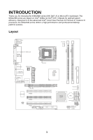
MSI 945GZM6 User Guide - Page 12
ATX 24-Pin Power Connector: ATX1, ATX 12V Power Connector: PWRCONN1, Floppy Disk Drive Connector:
 |
View all MSI 945GZM6 manuals
Add to My Manuals
Save this manual to your list of manuals |
Page 12 highlights
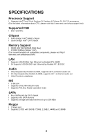
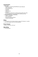
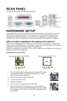
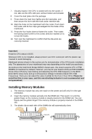
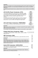
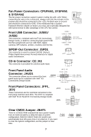
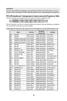
Important: DDR2 memory modules are not interchangeable with DDR and the DDR2 standard is not backwards compatible. You should always install DDR2 memory modules in the DDR2 DIMM slots. To enable successful system boot-up, always insert the memory modules into the DIMM1 first. ATX 24-Pin Power Connector: ATX1 This connector allows you to connect an ATX 24-pin power supply. To connect the ATX 24-pin power supply, make sure the plug of the power supply is inserted in the proper orientation and the pins are aligned. Then push down the power supply firmly into the connector. You may use the 20-pin ATX power supply as you like. If you like to use the 20-pin ATX power supply, please plug your power supply along with pin 1 & pin 13 (refer to the image at the right hand). +3 . 3V -1 2V GND PS -ON # GND GND GND Res +5V +5 V +5 V GND +3.3V +3.3V GND +5V GND +5V GND PWR OK 5VSB +12V +12V +3.3V ATX 12V Power Connector: PWRCONN1 +12V +12V This 12V power connector is used to provide power to the CPU. GND GND Important: Make sure that all the connectors are connected to proper ATX power supplies to ensure stable operation of the mainboard. Power supply of 350 watts (and above) is highly recommended for system stability. Floppy Disk Drive Connector: FDD1 This connector supports 360KB, 720KB, 1.2MB, 1.44MB or 2.88MB floppy disk drive. IDE Connector: IDE1 This connector supports IDE hard disk drives, optical disk drives and other IDE devices. Important: If you install two IDE devices on the same cable, you must configure the drives to cable select mode or separately to master / slave mode by setting jumpers. Refer to IDE device documentation supplied by the vendors for jumper setting instructions. Serial ATA Connector: SATA1/2/3/4 This connector is a high-speed Serial ATA interface port. Each connector can connect to one Serial ATA device. Important: Please do not fold the Serial ATA cable into 90-degree angle. Otherwise, data loss may occur during transmission. 6
-
 1
1 -
2
-
3
-
4
-
5
-
6
-
 7
7 -
 8
8 -
 9
9 -
 10
10 -
 11
11 -
 12
12 -
 13
13 -
 14
14 -
 15
15 -
 16
16 -
 17
17 -
18
-
19
-
20
-
21
-
22
-
23
-
24
-
25
-
26
-
27
-
28
-
29
-
30
-
31
-
32
-
33
-
34
-
35
-
36
-
37
-
38
-
39
-
40
-
41
-
42
-
43
-
44
-
45
-
46
-
47
-
48
-
49
-
50
-
51
-
52
-
53
-
54
-
55
-
56
-
57
-
58
-
59
-
60
-
61
-
62
-
63
-
64
-
65
-
66
-
67
-
68
-
69
-
70
-
71
-
72
-
73
-
74
-
75
-
76
-
77
-
78
-
79
-
80
-
81
-
82
-
83
-
84
-
85
-
86
-
87
-
88
-
89
-
90
-
91
-
92
-
93
-
94
 |
 |
