MSI 945GZM6 User Guide - Page 13
Fan Power Connectors: CPUFAN1, SYSFAN1
 |
View all MSI 945GZM6 manuals
Add to My Manuals
Save this manual to your list of manuals |
Page 13 highlights
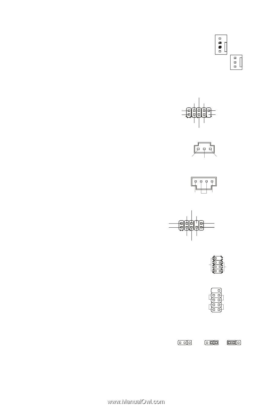
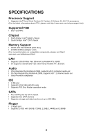
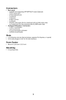
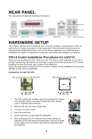
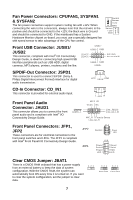
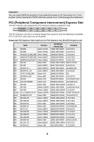
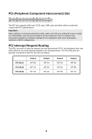
Fan Power Connectors: CPUFAN1, SYSFAN1 & SYSFAN2 The fan power connectors support system cooling fan with +12V. When connecting the wire to the connectors, always note that the red wire is the positive and should be connected to the +12V; the black wire is Ground and should be connected to GND. If the mainboard has a System Hardware Monitor chipset on-board, you must use a specially designed fan with speed sensor to take advantage of the CPU fan control. Control Sensor +12V GND Sensor +12V GND Front USB Connector: JUSB1/ JUSB2 This connector, compliant with Intel® I/O Connectivity Design Guide, is ideal for connecting high-speed USB interface peripherals such as USB HDD, digital cameras, MP3 players, printers, modems and the like. USB1+ USB1- GND (2)VCC (1)VCC N.C.(10) Key,no pin(9) USB0- GND USB0+ S/PDIF-Out Connector: JSPD1 This connector is used to connect S/PDIF (Sony & Philips Digital Interconnect Format) interface for digital audio transmission. VCC SPDIF GND CD-In Connector: CD_IN1 This connector is provided for external audio input. L GND R Front Panel Audio Connector: JAUD1 This connector allows you to connect the front panel audio and is compliant with Intel® I/O Connectivity Design Guide. (2)GND (1)MIC_L MIC2_JD VCC5 NC Line_JD(10) Line-out_L(9) MIC_R Front to Sense Line-out_R Front Panel Connectors: JFP1, JFP2 These connectors are for electrical connection to the front panel switches and LEDs. The JFP1 is compliant with Intel® Front Panel I/O Connectivity Design Guide. JFP2 JFP1 87 Speaker Power LED 21 10 9 + -- + -+ Power Reset Switch Switch Power HDD LED LED 21 Clear CMOS Jumper: JBAT1 There is a CMOS RAM onboard that has a power supply from an external battery to keep the data of system configuration. With the CMOS RAM, the system can automatically boot OS every time it is turned on. If you want to clear the system configuration, set the jumper to clear data. 3 21 3 21 3 21 Keep Data Clear Data 7
-
 1
1 -
2
-
3
-
4
-
5
-
6
-
7
-
 8
8 -
 9
9 -
 10
10 -
 11
11 -
 12
12 -
 13
13 -
 14
14 -
 15
15 -
 16
16 -
 17
17 -
 18
18 -
19
-
20
-
21
-
22
-
23
-
24
-
25
-
26
-
27
-
28
-
29
-
30
-
31
-
32
-
33
-
34
-
35
-
36
-
37
-
38
-
39
-
40
-
41
-
42
-
43
-
44
-
45
-
46
-
47
-
48
-
49
-
50
-
51
-
52
-
53
-
54
-
55
-
56
-
57
-
58
-
59
-
60
-
61
-
62
-
63
-
64
-
65
-
66
-
67
-
68
-
69
-
70
-
71
-
72
-
73
-
74
-
75
-
76
-
77
-
78
-
79
-
80
-
81
-
82
-
83
-
84
-
85
-
86
-
87
-
88
-
89
-
90
-
91
-
92
-
93
-
94
 |
 |