MSI GF615M User Guide - Page 18
mUsT ENTEr ThE BioS UTIlITY AND clEAr ThE rEcOrD.
 |
View all MSI GF615M manuals
Add to My Manuals
Save this manual to your list of manuals |
Page 18 highlights
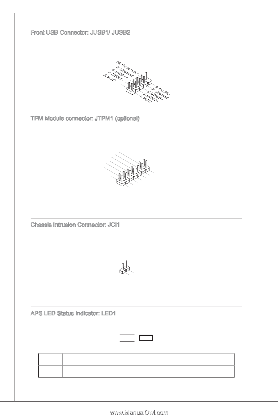
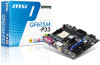
Front USB Connector: JUSB1/ JUSB2 This connector, compliant with Intel® I/O Connectivity Design Guide, is ideal for connecting high-speed USB interface peripherals such as USB HDD, digital cameras, MP3 players, printers, modems and the like. TPM Module connector: JTPM1 (optional) This connector connects to a TPM (Trusted Platform Module) module. Please re- fer to the TPM security platform manual for more details and usages. 2.34V.36S..3tS8aVe.n15Prd0iVaob1.NlwyP2I1o.eRopG4rwoPQ.rwGeionreurornudnd 1.L3P.L5CP.LCC7P.loLRC9cP.eLka1CsPd1e1ad.CtL3drPea.dLsdCrPsedasCr&edsFdsd&sraraedt&amsasdpteaa&intpa0dinap1tian2pin3 Chassis Intrusion Connector: JCI1 This connector connects to the chassis intrusion switch cable. If the chassis is opened, the chassis intrusion mechanism will be activated. The system will record this status and show a warning message on the screen. To clear the warning, you must enter the BIOS utility and clear the record. 1.C2.IGNTroRuUnd APS LED Status Indicator: LED1 These APS (Active Phase Switching) LED indicates the current CPU power phase mode. Follow the instructions below to read. LED1 ON OFF The LED will light when CPU is in 3 phase power mode. The LED off when CPU is in 1 phase power mode. 18
-
 1
1 -
2
-
3
-
4
-
5
-
6
-
7
-
8
-
9
-
10
-
11
-
12
-
 13
13 -
 14
14 -
 15
15 -
 16
16 -
 17
17 -
 18
18 -
 19
19 -
 20
20 -
 21
21 -
 22
22 -
 23
23 -
24
-
25
-
26
-
27
-
28
-
29
-
30
-
31
-
32
-
33
-
34
-
35
-
36
-
37
-
38
-
39
-
40
-
41
-
42
-
43
-
44
-
45
-
46
-
47
-
48
-
49
-
50
-
51
-
52
-
53
-
54
-
55
-
56
-
57
-
58
-
59
-
60
-
61
-
62
-
63
-
64
-
65
-
66
-
67
-
68
-
69
-
70
-
71
-
72
-
73
-
74
-
75
-
76
-
77
-
78
-
79
-
80
-
81
-
82
-
83
-
84
-
85
-
86
-
87
-
88
-
89
-
90
-
91
-
92
-
93
-
94
-
95
-
96
-
97
-
98
-
99
-
100
-
101
-
102
-
103
-
104
-
105
-
106
-
107
-
108
-
109
-
110
-
111
-
112
-
113
-
114
-
115
-
116
-
117
-
118
-
119
-
120
-
121
-
122
-
123
-
124
-
125
-
126
-
127
-
128
-
129
-
130
-
131
-
132
-
133
-
134
-
135
-
136
-
137
-
138
-
139
-
140
-
141
-
142
-
143
-
144
-
145
-
146
-
147
-
148
-
149
-
150
-
151
-
152
-
153
 |
 |