MSI K8MM-ILSR User Guide
MSI K8MM-ILSR - Motherboard - Micro ATX Manual
 |
UPC - 816909005738
View all MSI K8MM-ILSR manuals
Add to My Manuals
Save this manual to your list of manuals |
MSI K8MM-ILSR manual content summary:
- MSI K8MM-ILSR | User Guide - Page 1
K8TM / K8MM MS-6741 (v1.X) M-ATX Mainboard G52-M6741X4 i - MSI K8MM-ILSR | User Guide - Page 2
with the instruction manual, may cause user's authority to operate the equipment. Notice 2 Shielded interface cables and A.C. power cord, if any, must be used in order to comply with the emission limits. VOIR LA NOTICE D'INSTALLATION AVANT DE RACCORDER AU RESEAU. Micro-Star International MS-6741 - MSI K8MM-ILSR | User Guide - Page 3
Group. PCMCIA and CardBus are registered trademarks of the Personal Computer Memory Card International Association. Revision History Revision V1.0 V1.1 Revision History First release with chipset VIA K8T800 / K8M800 & VIA VT8237 Update AGP slot image Date September 2003 April 2004 iii - MSI K8MM-ILSR | User Guide - Page 4
guide, BIOS updates, driver updates, and other information: http://www.msi.com.tw & http://www.msi. com.tw/program/service/faq/faq/esc_faq_list.php h Contact our technical staff at: [email protected] Safety Instructions 1. Always read the safety instructions carefully. 2. Keep this User's Manual - MSI K8MM-ILSR | User Guide - Page 5
1. Getting Started 1-1 Mainboard Specifications 1-2 Mainboard Layout 1-4 Chapter 2. Hardware Setup 2-1 Quick Components Guide 2-2 Central Processing Unit: CPU 2-3 Memory Speed/CPU FSB Support Matrix 2-3 CPU Installation Procedures for Socket 754 2-4 Installing AMD Athlon64 CPU Cooler Set - MSI K8MM-ILSR | User Guide - Page 6
3-18 PC Health Status 3-20 Frequency/Voltage Control 3-21 Set Supervisor/User Password 3-23 Load High Performance/BIOS Setup Defaults 3-24 Appendix A: Using 4- or 6-Channel Audio Function A-1 Installing the Audio Driver A-2 Installation for Windows 98SE/ME/2000/XP A-2 Using 4- or 6-Channel - MSI K8MM-ILSR | User Guide - Page 7
Testing the Connected Speakers A-9 Testing Each Speaker A-9 Playing KaraOK A-11 Playing KaraOK A-11 Appendix B: VIA VT8237 Serial ATA RAID Introduction B-1 Introduction ...B-2 BIOS Configuration B-3 Installing RAID Software & Drivers B-11 Using VIA RAID Tool B-13 vii - MSI K8MM-ILSR | User Guide - Page 8
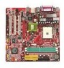
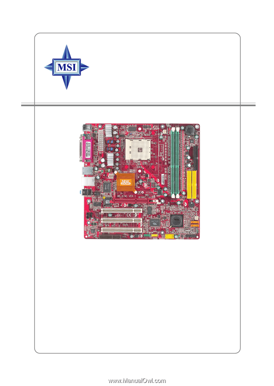
the K8TM/K8MM (MS-6741 v1.x), an excellent Micro-ATX mainboard from MSI. Based on the innovative VIA K8T800 / K8M800 and VIA VT8237 chipsets for optimal system efficiency, the K8TM mainboard accommodates latest AMD K8 processor in the 754-pin lidded ceramic micro PGA package, and supports up to - MSI K8MM-ILSR | User Guide - Page 9
MS-6741 Micro-ATX Mainboard Mainboard Specifications CPU Supports 64-bit AMD® K8 Athlon 64 processor (Socket 754). Supports 3100+, 3200+ or higher CPU. Chipset VIA K8T 800/K8M800 Chipset (578-pin BGA) -HyperTransportTM connection to AMD K8 Athlon64 processor -8 or 16 bit control/address/data - MSI K8MM-ILSR | User Guide - Page 10
AC97 v2.3 Spec. - Meet PC2001 audio performance requirement. LAN VIA VT8237 MAC + VIA 6103 Ethernet PHY - Supports 10/100Mb/s auto-negotiation operation. - Compliant with PCI v2.2 and PC99 standard. - Supports ACPI Power Management. BIOS The mainboard BIOS provides "Plug & Play" BIOS which detects - MSI K8MM-ILSR | User Guide - Page 11
Winbond 83697HF VIA VT6103 BIOS JSP1 JIR1 JCD1 JAUD1 KV8VTIIA8A00 K/K88TM880000 /K8M800 AGP Slot PCI Slot 1 PCI Slot 2 PCI Slot 3 Codec CNR J1394_1 VIA VT6307 JUSB1 DDR 1 DDR 2 IDE 1 IDE 2 VIA 8237 JUSB2 SFAN1 S ATA 2 S ATA 1 J B AT 1 JFP1 JFP2 K8TM/K8MM (MS-6741 v1.X) Mainboard 1-4 - MSI K8MM-ILSR | User Guide - Page 12
Hardware Setup Chapter 2. Hardware Setup Hardware Setup This chapter provides you with the information about hardware setup procedures. While doing the installation, be careful in holding the components and follow the installation procedures. For some components, if you install in the wrong - MSI K8MM-ILSR | User Guide - Page 13
MS-6741 Micro-ATX Mainboard Quick Components Guide JPWR1, p.2-9 CPU, p.2-3 CFAN1, p.2-14 DDR1-2, p.2-7 I/O Ports, p.2-10 JPW1, p.2-9 B AT T + FDD1, p.2-14 IDE1, IDE2, p.2-15 JSP1, p.2-19 JCD1, p.2-17 JIR1, p.2-18 JAUD1, p.2-18 CNR slot, p.2-21 AGP slot, p.2- - MSI K8MM-ILSR | User Guide - Page 14
first to ensure the safety of CPU. Overclocking This motherboard is designed to support overclocking. However, please make sure your components are able to tolerate such abnormal setting, while doing overclocking. Any attempt to operate beyond product specifications is not recommended. We do not - MSI K8MM-ILSR | User Guide - Page 15
MS-6741 Micro-ATX Mainboard CPU Installation Procedures for Socket 754 1. Please turn off the power and unplug the power cord before installing the CPU. 2. Pull the lever sideways away from the socket. Make sure to raise the lever up to a 90-degree angle. 3. Look for the gold arrow. The gold arrow - MSI K8MM-ILSR | User Guide - Page 16
Hardware Setup Installing AMD Athlon64 CPU Cooler Set When you are installing the CPU, make sure the CPU has a heat sink and a cooling fan attached on the top to prevent overheating. If you do not have the heat sink and cooling fan, contact - MSI K8MM-ILSR | User Guide - Page 17
MS-6741 Micro-ATX Mainboard 5. Position the cooling set onto the retention mechanism. Hook one end of the clip to hook Fixed Bolt. Lift up the intensive fixed lever. Safety Hook Fixed Lever Fixed Bolt 2-6 MSI Reminds You... While disconnecting the Safety Hook from the fixed bolt, it is necessary to - MSI K8MM-ILSR | User Guide - Page 18
The mainboard provides two slots for 184-pin DDR SDRAM DIMM (Double In-Line Memory Module) modules and supports up to 2GB memory size. You can install PC2700/DDR333 & PC2100/DDR266 modules on the DDR DIMM slots (DDR 1~2). DDR DIMM Slots (DDR1~2) Introduction to DDR SDRAM DDR (Double - MSI K8MM-ILSR | User Guide - Page 19
MS-6741 Micro-ATX Mainboard DDR DIMM Module Combination Install at least one DIMM module on the slots. Memory modules can be installed on the slots in any order. You can install either single- or double-sided modules to meet your own needs. Memory modules can be installed in any combination as - MSI K8MM-ILSR | User Guide - Page 20
JPW1 Pin Definition MSI Reminds You... There is a mechanism of this mainboard to protect it from being damaged. The power will shut down automatically in two conditions: the temperature of CPU reaches 100oC, or the low voltage occurs during booting up. Please follow the instructions below for this - MSI K8MM-ILSR | User Guide - Page 21
MS-6741 Micro-ATX Mainboard Back Panel View of the Back Panel The back panel provides the following connectors: Mouse Parallel 1394 LAN L-in Port (Optional) Keyboard COM A VGA Port USB Ports USB Ports L-out (Optional) MIC Serial Port: COMA The mainboard provides one 9-pin mail DIN - MSI K8MM-ILSR | User Guide - Page 22
6 NC DESCRIPTION Keyboard data No connection Ground +5V Keyboard clock No connection VGA Connector The mainboard provides a DB 15-pin female connector to connect a VGA monitor. 5 1 15 11 VGA Connector (DB 15-pin) Pin Definition Pin Signal Description Pin Signal Description 1 RED - MSI K8MM-ILSR | User Guide - Page 23
MS-6741 Micro-ATX Mainboard USB Ports The mainboard provides a LAN Jack (Optional) The mainboard provides one standard RJ-45 jack for connection to Local Area Network (LAN). You can connect a network cable to the LAN jack. Activity Indicator Link Indicator 2-12 8 1 RJ-45 LAN Jack 10/100 LAN - MSI K8MM-ILSR | User Guide - Page 24
Setup IEEE 1394 Port (Optional) The mainboard provides one IEEE 1394 port, which connects to IEEE 1394 devices -pin female centronic connector as LPT. A parallel port is a standard printer port that supports Enhanced Parallel Port (EPP) and Extended Capabilities Parallel Port (ECP) mode. 13 1 - MSI K8MM-ILSR | User Guide - Page 25
MS-6741 Micro-ATX Mainboard Connectors The mainboard provides connectors to connect FDD, IDE HDD, front panel of the system case, audio ports, USB Ports, and CPU/System FANs. Floppy Disk Drive Connector: FDD1 The mainboard provides a standard floppy disk drive connector that supports 360KB, 720KB, - MSI K8MM-ILSR | User Guide - Page 26
and Ultra DMA 33/66/100/133 controller that supports PIO mode 0 ~ 4, Bus Master, and drive (reserved for future BIOS), and other devices. IDE1 IDE2 MSI Reminds You... If you instructions. Front USB Connectors: JUSB1 & JUSB2 The mainboard provide two front Universal Serial Bus connectors for users - MSI K8MM-ILSR | User Guide - Page 27
MS-6741 Micro-ATX Mainboard Serial ATA/Serial ATA RAID Connectors controlled by VT8237: SATA1 & SATA2 The Southbridge of this mainboard is VIA VT8237 which supports two serial connectors SATA1& SATA2. SATA1 & SATA2 are dual high-speed Serial ATA interface ports. Each supports 1st generation serial - MSI K8MM-ILSR | User Guide - Page 28
panel connectors for electrical connection to the front panel switches and LEDs. JFP2 is compliant with Intel® Front Panel I/O Connectivity Design Guide. Power Power LED Switch JFP2 2 1 10 9 HDD Reset LED Switch Speaker JFP1 2 1 8 7 Power LED JFP2 Pin Definition PIN SIGNAL 1 HD_LED_P - MSI K8MM-ILSR | User Guide - Page 29
MS-6741 Micro-ATX Mainboard Front Panel Audio Connector: JAUD1 The mainboard provides one front audio connector for users audio signal return from front panel MSI Reminds You... If you don't BIOS setup to use the IR function. JIR1 is compliant with Intel® Front Panel I/O Connectivity Design Guide - MSI K8MM-ILSR | User Guide - Page 30
Hardware Setup IEEE 1394 Connector: J1394_1 The mainboard provides one IEEE1394 pin header that allows you to connect IEEE 1394 port via an external IEEE1394 bracket (optional). 9 1 10 2 J1394_1 Connected to J1394_1 Pin Definition PIN - MSI K8MM-ILSR | User Guide - Page 31
MS-6741 Micro-ATX Mainboard Jumpers The mainboard provides the following jumpers for you to set the computer's function. This section will explain how to change your mainboard's function through the use of jumpers. Clear CMOS Jumper: JBAT1 There is a CMOS RAM on board that has a power supply from - MSI K8MM-ILSR | User Guide - Page 32
to insert the AGP graphics card. AGP is an interface specification designed for the throughput demands of 3D graphics. It introduces a 66MHz, 32-bit channel for the graphics controller to directly access main memory. The slot supports 8x/4x AGP card. PCI (Peripheral Component Interconnect) Slots - MSI K8MM-ILSR | User Guide - Page 33
This chapter provides information on the BIOS Setup program and allows you to configure the system for optimum use. You may need to run the Setup program when: ” An error message appears - MSI K8MM-ILSR | User Guide - Page 34
MS-6741 Micro-ATX You are allowed to select the 1st boot device without entering the BIOS setup utility by pressing . When the same message as listed ESC] cancel The boot menu will list all the bootable devices. Select the one you want to boot from by using arrow keys, and then press - MSI K8MM-ILSR | User Guide - Page 35
value or make changes Decrease the numeric value or make changes Load BIOS Setup Defaults Load High Performance Defaults Save all the CMOS changes and is the Main Menu. Main Menu The main menu displays the setup categories the BIOS supplies. You can use the arrow keys ( Ż ) to select the item. - MSI K8MM-ILSR | User Guide - Page 36
MS-6741 Micro-ATX this menu for basic system configurations, such as time, date etc. Advanced BIOS Features Use this menu to setup the items of AMI® special enhanced features. . PNP/PCI Configurations This entry appears if your system supports PnP/PCI. Integrated Peripherals Use this menu to specify - MSI K8MM-ILSR | User Guide - Page 37
for frequency/voltage control. Set Supervisor Password Use this menu to set Supervisor Password. Set User Password Use this menu to set User Password. Load High Performance Defaults Use this menu to load the BIOS values for the best system performance, but the system stability may be affected. Load - MSI K8MM-ILSR | User Guide - Page 38
MS-6741 Micro-ATX Mainboard Standard CMOS Features The items inside STANDARD CMOS SETUP menu are divided into 9 categories. Each category includes none, one or more setup items. Use the arrow keys to highlight the item you want to modify and use the or keys to switch - MSI K8MM-ILSR | User Guide - Page 39
BIOS Setup LBA Mode Block Mode Fast Programmed I/O Modes 32 Bit Transfer Mode Protection The item is to set the Virus Warning feature for IDE Hard Disk boot sector protection. When Enabled, BIOS will issue a virus warning message and beep if a write to the boot sector or the partition table of - MSI K8MM-ILSR | User Guide - Page 40
MS-6741 Micro-ATX Mainboard Advanced BIOS Features Quick Boot Setting the item to Enabled allows Device The items allow you to set the sequence of boot devices where BIOS attempts to load the disk operating system. MSI Reminds You... Available settings for "1st/2nd/3rd Boot Device" vary depending - MSI K8MM-ILSR | User Guide - Page 41
powered on. Setting to Off will allow end users to use the arrow keys on the numeric the BIOS to search for floppy disk drives at boot time. When enabled, the BIOS CGA40x25, CGA80x25, VGA/EGA, Absent memory is additional memory that is much faster than conventional DRAM (system memory). When the CPU - MSI K8MM-ILSR | User Guide - Page 42
MS-6741 Micro-ATX Mainboard memory. When the CPU requests data, the system transfers the requested data from the main DRAM into cache memory, for even faster access by the CPU. Setting options: Enabled, Disabled. System BIOS Cacheable Selecting Enabled allows caching of the system BIOS ROM at - MSI K8MM-ILSR | User Guide - Page 43
BIOS Setup Advanced Chipset Features MSI Reminds You... Change these settings only if you are familiar with the users to configure these fields manually. Memclock Value When it is set to Limit in "Memclock Mode", user can place an artificial memory clock limit on the system. Please note that memory - MSI K8MM-ILSR | User Guide - Page 44
MS-6741 Micro-ATX Mainboard Burst Length This setting allows you to set the size of Burst-Length for DRAM. Bursting feature is a technique that DRAM itself predicts the address of the next memory location to be accessed after the first address is accessed. To use the feature, you need to define the - MSI K8MM-ILSR | User Guide - Page 45
lost (CPU or BIOS to call VGA BIOS to initialize the VGA card when system wakes up (resumes) from S3 sleep state. The system resume time is shortened when you disable the function, but system will need an AGP driver to initialize the VGA card. Therefore, if the AGP driver of the card does not support - MSI K8MM-ILSR | User Guide - Page 46
MS-6741 Micro-ATX Mainboard USB Wakeup From S3 This item allows the activity of the USB device to wake up the system from S3 (Suspend to RAM CPU shut off. Settings: Disabled, 1, 2, 4, 8, 10, 20, 30, 40, 50, 60. Display Activity These items specify if the BIOS the CPU overheating problem. Power - MSI K8MM-ILSR | User Guide - Page 47
BIOS Setup Wake Up On PME, Resume On KBC (with "Wake-Up Key" and " of the specified hardware peripheral or component is detected. Settings: Enabled, Disabled. MSI Reminds You... For "Wake-Up Key" function, the option "Specific Key" refers to the password you specify in the "Wake-Up Password" field - MSI K8MM-ILSR | User Guide - Page 48
MS-6741 Micro-ATX Mainboard PNP/PCI Configurations This section describes configuring the PCI bus system and PnP (Plug & Play) feature. PCI, or Peripheral Component Interconnect, is a system which allows I/O devices to operate at speeds nearing the speed the CPU itself uses when communicating with - MSI K8MM-ILSR | User Guide - Page 49
card first. If the PCI VGA card is not available, it will initialize the AGP card. PCI Slot1 IRQ, PCI Slot2 IRQ, PCI Slot3 IRQ These items specify the IRQ line for each PCI slot. Setting options: 3, 4, 5, 7, 9, 10, 11, Auto. Selecting Auto allows BIOS to automatically determine the IRQ line for - MSI K8MM-ILSR | User Guide - Page 50
MS-6741 Micro-ATX Mainboard Integrated Peripherals Floopy Disk Controller This is used to enable or disable the onboard Floppy controller. Option Auto Enabled Disabled Description BIOS will automatically determine whether to enable the onboard Floppy controller or not. Enables the onboard Floppy - MSI K8MM-ILSR | User Guide - Page 51
show Auto indicating that BIOS automatically determines the DMA SATA-IDE controller. Setting options: Disabled, Enabled. V-Link Data 2X Support This setting controls the onboard V-Link Data 2X Support. Setting options: Enabled, Disabled. OnBoard LAN, OnBoard LAN not support or have any USB driver - MSI K8MM-ILSR | User Guide - Page 52
MS-6741 Micro-ATX Mainboard PC Health Status This section shows the status of your CPU, fan, overall system status, of the field will automatically return to Enabled later. Settings: Enabled, Reset, Disabled. CPU/System Temperature, CPU/System Fan Speed, Vcore, +5.0V, +12.0V, 12.0V, -5.0V, Battery, - MSI K8MM-ILSR | User Guide - Page 53
FSB Clock This item allows you to select the CPU Front Side Bus clock frequency (in MHz) and overclock the processor by adjusting the FSB clock to a higher frequency. Select the number between 200~280 for needed frequency. MSI Reminds You... Changing CPU FSB clock could result in the instability of - MSI K8MM-ILSR | User Guide - Page 54
MS-6741 Micro-ATX Mainboard DDR Voltage (V) Adjusting the DDR voltage can increase the the performance of your AGP display card when overclocking, but the stability may be affected. Setting options: Auto, 1.55, 1.60, 1.65, 1.70, 1.75, 1.80, 1.85. MSI Reminds You... The settings shown in different - MSI K8MM-ILSR | User Guide - Page 55
BIOS Setup Set Supervisor/User Password When you select this function, a message as below will appear on the screen: Type the password, up to six characters in length, and press . The password typed now will replace any previously set password from CMOS memory. You will be prompted to - MSI K8MM-ILSR | User Guide - Page 56
MS-6741 Micro-ATX Mainboard Load High Performance/BIOS Setup Defaults The two options on the main menu allow users to restore all of the BIOS settings to High Performance defaults or BIOS Setup defaults. The High Performance Defaults are the values set by the mainboard manufacturer for the best - MSI K8MM-ILSR | User Guide - Page 57
Using 4- or 6-Channel Audio Function Appendix A: Using 4- or 6-Channel Audio Function The motherboard is equipped with Realtek ALC655 chip, which provides support for 6-channel audio output, including 2 Front, 2 Rear, 1 Center and 1 Subwoofer channel. ALC655 allows the board to attach 4 or 6 - MSI K8MM-ILSR | User Guide - Page 58
MS-6741 Micro-ATX Mainboard Installing the Audio Driver You need to install the driver for Realtek ALC655 chip to function properly before you can get access to 4-/6-channel audio operations. Follow the procedures described below to install the drivers for different operating systems. Installation - MSI K8MM-ILSR | User Guide - Page 59
Using 4- or 6-Channel Audio Function 3. Click Next to start installing files into the system. 4. Click Finish to restart the system. Select this option A-3 - MSI K8MM-ILSR | User Guide - Page 60
MS-6741 Micro-ATX Mainboard Using 4- or 6-Channel Audio Function After installing the audio driver, you are able to use the 4-/6-channel audio feature now. To enable 4- or 6-channel audio operation, first connect 4 or 6 speakers to the appropriate audio connectors, - MSI K8MM-ILSR | User Guide - Page 61
Using 4- or 6-Channel Audio Function A-5 - MSI K8MM-ILSR | User Guide - Page 62
MS-6741 Micro-ATX Mainboard Connecting the Speakers When you have set the Multi-Channel Audio Function mode properly in the software utility, connect your speakers to the correct - MSI K8MM-ILSR | User Guide - Page 63
Using 4- or 6-Channel Audio Function „ 4-Channel Mode for 4-Speaker Output The audio jacks on the back panel always provide 2-channel analog audio output function, however these audio jacks can be transformed to 4- or 6- channel analog audio jacks by selecting the corresponding multi-channel - MSI K8MM-ILSR | User Guide - Page 64
MS-6741 Micro-ATX Mainboard „ 6-Channel Mode for 6-Speaker Output Refer to the function are converted to Line Out function when 4-Channel Mode for 6-Speaker Output is 3 selected. MSI Reminds You... If the Center and Subwoofer speaker exchange their audio channels when you play video or music - MSI K8MM-ILSR | User Guide - Page 65
is inserted firmly to the connector or replace the bad speakers with good ones. Testing Each Speaker 1. Click the audio icon screen. from the window it. Front Left Center Front Right Rear Right Rear Left Subwoofer MSI Reminds You... 6 speakers appear on the "Speaker Test" window only - MSI K8MM-ILSR | User Guide - Page 66
MS-6741 Micro-ATX Mainboard 4. While you are testing the speakers in 6-Channel Mode, if the sound coming from the center speaker and subwoofer is swapped, you should select Swap Center/ Subwoofer Output to readjust these two channels. Select this function A-10 - MSI K8MM-ILSR | User Guide - Page 67
Using 4- or 6-Channel Audio Function Playing KaraOK The KaraOK function will automatically remove human voice (lyrics) and leave melody for you to sing the song. Note that this function applies only for 2-channel audio operation. Playing KaraOK 1. Click the audio icon screen. from the window - MSI K8MM-ILSR | User Guide - Page 68
9. Windows-based RAID configure and management software tool. (Compatible with BIOS) 10. Supports hot-swap failed disk drive in RAID 1 array. 11. ATA SMART function support. 12. Microsoft Windows 98, Me, NT4.0, 2000, XP operating systems support. 13. Event log for easy troubleshooting. B-1 - MSI K8MM-ILSR | User Guide - Page 69
MS-6741 M-ATX Mainboard Introduction This section gives a brief introduction on the RAID-related background knowledge and a brief introduction on VIA SATA RAID Host Controller. For users wishing to install their VIA SATA RAID driver and RAID software, proceed to Driver one support fault tolerance. RAID - MSI K8MM-ILSR | User Guide - Page 70
the system powers on during the POST (Power-On Self Test) process, press key to enter the BIOS configuration. The Serial ATA RAID volume may be configured using the VIA Tech. RAID BIOS. Always use the arrow keys to navigate the main menu, use up and down arrow key to select - MSI K8MM-ILSR | User Guide - Page 71
MS-6741 M-ATX Mainboard Create Disk Array Use the up and down arrow keys to select the Create Array command and press . MSI Reminds You... option list will popup and enable the users to select Create only or Create and duplicate. Create only will allow BIOS to only create an array. The data - MSI K8MM-ILSR | User Guide - Page 72
is "Select Disk Drives". Auto Setup allows BIOS to select the disk drives and create arrays automatically, but it does not duplicate the mirroring drives even if the user selected Create and duplicate for RAID 1. It is recommended all disk drives are new ones when wanting to create an array. Select - MSI K8MM-ILSR | User Guide - Page 73
MS-6741 M-ATX Mainboard MSI Reminds You... Even though 64KB is the recommended setting for most users, you should choose the block size value which is best suited to your specific RAID usage model. 4KB: For specialized usage models requiring 4KB blocks 8KB: For specialized usage models requiring - MSI K8MM-ILSR | User Guide - Page 74
RAID Introduction Create and Delete Spare Hard Drive If a RAID 1 array is created and there are drives that do not belong to other arrays, the one that has a capacity which is equal to or greater than the array capacity can be selected as a spare drive for the RAID 1 array. Select Create - MSI K8MM-ILSR | User Guide - Page 75
MS-6741 M-ATX Mainboard Duplicate Critical RAID 1 Array When booting up the system, BIOS will detect if the RAID 1 array has any inconsistencies between user data and backup data. If BIOS detects any inconsistencies, the status of the disk array will be marked as critical, and BIOS will prompt the - MSI K8MM-ILSR | User Guide - Page 76
one. If your computer does not support APM, you must turn off your computer manually. After replacing the hard drive, boot into BIOS Choose Replacement Drive and Rebuild: This item enables users to select an already-connected hard drive to BIOS to skip the problem and continue booting into OS. B-9 - MSI K8MM-ILSR | User Guide - Page 77
MS-6741 M-ATX Mainboard Installing RAID Software & Drivers Install Driver in Windows OS h New Windows OS (2000/XP/NT4) Installation The following details the installation of the drivers while installing Windows XP. 1. Start the installation: Boot from the CD-ROM. Press F6 when the message "Press F6 - MSI K8MM-ILSR | User Guide - Page 78
the Windows* XP operating system. This version of VIA SATA RAID Utility contains the following key features: h Serial ATA RAID driver for Windows XP h VIA SATA RAID utility h RAID0 and RAID1 functions Insert the MSI CD and click on the VIA SATA RAID Utility to install the software. The InstallShield - MSI K8MM-ILSR | User Guide - Page 79
MS-6741 M-ATX Mainboard Put a check mark in the check box to install the feature you want. Then click Next button to proceed the installation. B-12 - MSI K8MM-ILSR | User Guide - Page 80
main interface is divided into two windows and the toolbar above contain the main functions. Click on these toolbar buttons to execute their specific functions. The left windowpane displays the controller and disk drives and the right windowpane displays the details of the controller or disk drives - MSI K8MM-ILSR | User Guide - Page 81
MS-6741 M-ATX Mainboard Click on or button to determine the viewing type of left window pane. There are two viewing types: By controllers and by device. Click - MSI K8MM-ILSR | User Guide - Page 82
VIA VT8237 Serial ATA RAID Introduction You may also use the same --RAID 1. or button to view the statuses of Array 0- Click on the plus (+) symbol next to Array 0---RAID 1 to see the details of each disk. B-15
-
 1
1 -
 2
2 -
 3
3 -
 4
4 -
 5
5 -
 6
6 -
 7
7 -
8
-
9
-
10
-
11
-
12
-
13
-
14
-
15
-
16
-
17
-
18
-
19
-
20
-
21
-
22
-
23
-
24
-
25
-
26
-
27
-
28
-
29
-
30
-
31
-
32
-
33
-
34
-
35
-
36
-
37
-
38
-
39
-
40
-
41
-
42
-
43
-
44
-
45
-
46
-
47
-
48
-
49
-
50
-
51
-
52
-
53
-
54
-
55
-
56
-
57
-
58
-
59
-
60
-
61
-
62
-
63
-
64
-
65
-
66
-
67
-
68
-
69
-
70
-
71
-
72
-
73
-
74
-
75
-
76
-
77
-
78
-
79
-
80
-
81
-
82
 |
 |
K8TM / K8MM
G52-M6741X4
MS-6741 (v1.X) M-ATX Mainboard