MSI K8MM-ILSR User Guide - Page 23
RJ-45 LAN Jack Optional, USB Ports, RJ-45 LAN Jack
 |
UPC - 816909005738
View all MSI K8MM-ILSR manuals
Add to My Manuals
Save this manual to your list of manuals |
Page 23 highlights
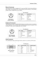
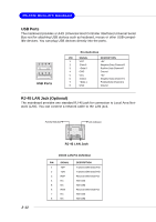
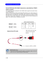
MS-6741 Micro-ATX Mainboard USB Ports The mainboard provides a UHCI (Universal Host Controller Interface) Universal Serial Bus root for attaching USB devices such as keyboard, mouse or other USB-compatible devices. You can plug USB devices directly into the ports. 1 2 3 4 5 6 7 8 USB Ports Pin Definition PIN SIGNAL 1 VCC 2 -Data 0 3 +Data 0 4 GND 5 VCC 6 -Data 1 7 +Data 1 8 GND DESCRIPTION +5V Negative Data Channel 0 Positive Data Channel 0 Ground +5V Negative Data Channel 1 Positive Data Channel 1 Ground RJ-45 LAN Jack (Optional) The mainboard provides one standard RJ-45 jack for connection to Local Area Network (LAN). You can connect a network cable to the LAN jack. Activity Indicator Link Indicator 2-12 8 1 RJ-45 LAN Jack 10/100 LAN Pin Definition PIN SIGNAL 1 TDP 2 TDN 3 RDP 4 NC 5 NC 6 RDN 7 NC 8 NC DESCRIPTION Transmit Differential Pair Transmit Differential Pair Receive Differential Pair Not Used Not Used Receive Differential Pair Not Used Not Used
-
 1
1 -
2
-
3
-
4
-
5
-
6
-
7
-
8
-
9
-
10
-
11
-
12
-
13
-
14
-
15
-
16
-
17
-
 18
18 -
 19
19 -
 20
20 -
 21
21 -
 22
22 -
 23
23 -
 24
24 -
 25
25 -
 26
26 -
 27
27 -
 28
28 -
29
-
30
-
31
-
32
-
33
-
34
-
35
-
36
-
37
-
38
-
39
-
40
-
41
-
42
-
43
-
44
-
45
-
46
-
47
-
48
-
49
-
50
-
51
-
52
-
53
-
54
-
55
-
56
-
57
-
58
-
59
-
60
-
61
-
62
-
63
-
64
-
65
-
66
-
67
-
68
-
69
-
70
-
71
-
72
-
73
-
74
-
75
-
76
-
77
-
78
-
79
-
80
-
81
-
82
 |
 |
