MSI K8MM-ILSR User Guide - Page 20
Power Supply, ATX 20-Pin Power Connector: JWR1 - cpu support
 |
UPC - 816909005738
View all MSI K8MM-ILSR manuals
Add to My Manuals
Save this manual to your list of manuals |
Page 20 highlights
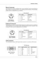
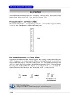
Hardware Setup Power Supply The mainboard supports ATX power supply for the power system. Before inserting the power supply connector, always make sure that all components are installed properly to ensure that no damage will be caused. ATX 20-Pin Power Connector: JWR1 This connector allows you to connect to an ATX power supply. To connect to the ATX power supply, make sure the plug of the power supply is inserted in the proper orientation and the pins are aligned. Then push down the power supply firmly into the connector. JWR1 Pin Definition 11 1 PIN SIGNAL PIN SIGNAL 20 10 JWR1 1 3.3V 2 3.3V 3 GND 4 5V 5 GND 6 5V 7 GND 8 PW_OK 9 5V_SB 10 12V 11 3.3V 12 -12V 13 GND 14 PS_ON 15 GND 16 GND 17 GND 18 -5V 19 5V 20 5V ATX 12V Power Connector: JPW1 This 12V power connector is used to provide power to the CPU. 42 31 JPW1 PIN SIGNAL 1 GND 2 GND 3 12V 4 12V JPW1 Pin Definition MSI Reminds You... There is a mechanism of this mainboard to protect it from being damaged. The power will shut down automatically in two conditions: the temperature of CPU reaches 100oC, or the low voltage occurs during booting up. Please follow the instructions below for this issue: 1. The power LED will blink continously. You should unplug the power cord or turn off the power switch. 2. After the power LED stop blinking, plug on the power cord or turn on the power switch, then you can reboot your system again. 2-9
-
 1
1 -
2
-
3
-
4
-
5
-
6
-
7
-
8
-
9
-
10
-
11
-
12
-
13
-
14
-
 15
15 -
 16
16 -
 17
17 -
 18
18 -
 19
19 -
 20
20 -
 21
21 -
 22
22 -
 23
23 -
 24
24 -
 25
25 -
26
-
27
-
28
-
29
-
30
-
31
-
32
-
33
-
34
-
35
-
36
-
37
-
38
-
39
-
40
-
41
-
42
-
43
-
44
-
45
-
46
-
47
-
48
-
49
-
50
-
51
-
52
-
53
-
54
-
55
-
56
-
57
-
58
-
59
-
60
-
61
-
62
-
63
-
64
-
65
-
66
-
67
-
68
-
69
-
70
-
71
-
72
-
73
-
74
-
75
-
76
-
77
-
78
-
79
-
80
-
81
-
82
 |
 |
