MSI K9AGM2-FIH User Guide - Page 33
SPDIF-Out / SPDIF-In Connector: SPDOUT1 / SPDIN1 Optional, JSPI Debugging Pin Header: JSPI1
 |
UPC - 816909038378
View all MSI K9AGM2-FIH manuals
Add to My Manuals
Save this manual to your list of manuals |
Page 33 highlights
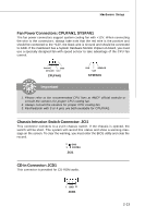
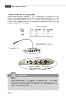
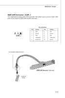
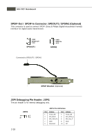
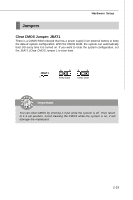
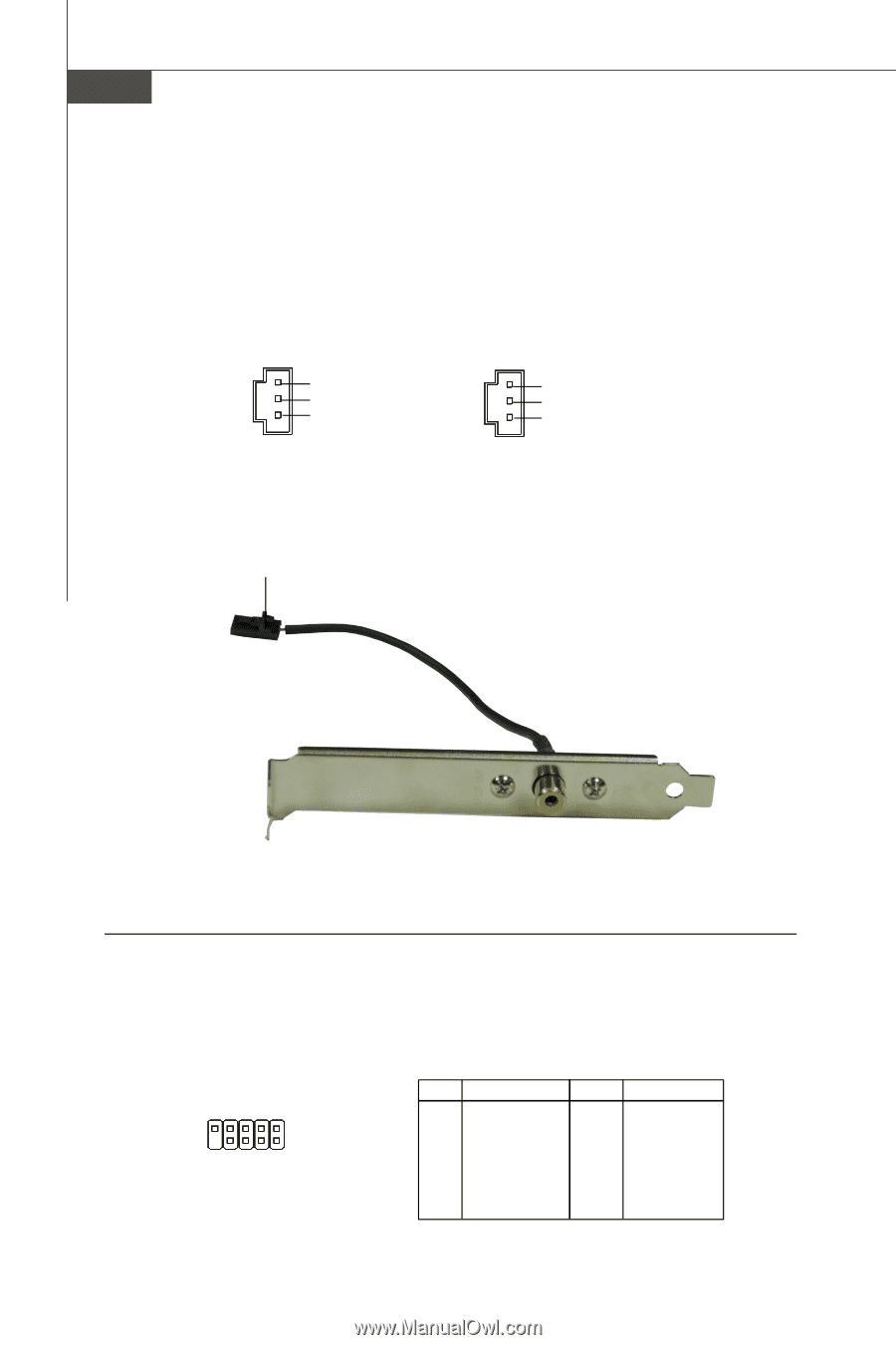
MS-7327 Mainboard SPDIF-Out / SPDIF-In Connector: SPDOUT1 / SPDIN1 (Optional) This connector is used to connect SPDIF (Sony & Philips Digital Interconnect Format) interface for digital audio transmission. GND SPDIF OUT VCC SPDOUT1 GND SPDIF IN VCC SPDIN1 Connected to SPDOUT1 / SPDIN1 SPDIF Bracket (Optional) JSPI Debugging Pin Header: JSPI1 The pin header is for internal debugging only. JSPI1 9 1 10 2 JSPI1 Pin Definition PIN SIGNAL 1 VCC3_SB 3 SPI_MISO 5 SPI_CSO_F# 7 GND 9 Reserved PIN SIGNAL 2 VCC3_SB 4 SPI_MOSI_F 6 SPI_CLK_F 8 GND 10 NC 2-18
-
 1
1 -
2
-
3
-
4
-
5
-
6
-
7
-
8
-
9
-
10
-
11
-
12
-
13
-
14
-
15
-
16
-
17
-
18
-
19
-
20
-
21
-
22
-
23
-
24
-
25
-
26
-
27
-
 28
28 -
 29
29 -
 30
30 -
 31
31 -
 32
32 -
 33
33 -
 34
34 -
 35
35 -
 36
36 -
 37
37 -
 38
38 -
39
-
40
-
41
-
42
-
43
-
44
-
45
-
46
-
47
-
48
-
49
-
50
-
51
-
52
-
53
-
54
-
55
-
56
-
57
-
58
-
59
-
60
-
61
-
62
-
63
-
64
-
65
-
66
-
67
-
68
-
69
-
70
-
71
-
72
-
73
-
74
-
75
-
76
-
77
-
78
-
79
-
80
-
81
-
82
-
83
-
84
-
85
-
86
-
87
-
88
-
89
 |
 |
2-18
MS-7327 Mainboard
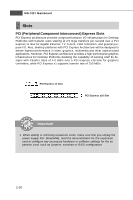
Connected to SPDOUT1 / SPDIN1
SPDIF Bracket
(Optional)
SPDIF-Out / SPDIF-In Connector: SPDOUT1 / SPDIN1 (Optional)
This connector is used to connect SPDIF (Sony & Philips Digital Interconnect Format)
interface for digital audio transmission.
SPDOUT1
GND
SPDIF OUT
VCC
SPDIN1
GND
SPDIF IN
VCC
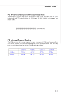
JSPI Debugging Pin Header: JSPI1
The pin header is for internal debugging only.
JSPI1 Pin Definition
PIN
SIGNAL
PIN
SIGNAL
1
VCC3_SB
2
VCC3_SB
3
SPI_MISO
4
SPI_MOSI_F
5
SPI_CSO_F#
6
SPI_CLK_F
7
GND
8
GND
9
Reserved
10
NC
JSPI1
9
10
2
1