MSI K9N2 User Guide - Page 22
Power Supply - cpu
 |
UPC - 816909044867
View all MSI K9N2 manuals
Add to My Manuals
Save this manual to your list of manuals |
Page 22 highlights
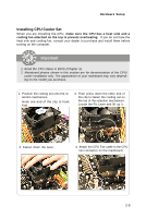
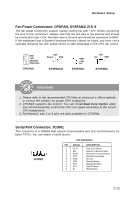
MS-7375 Mainboard Power Supply ATX 24-Pin Power Connector: ATX1 This connector allows you to connect an ATX 24-pin power supply. To connect the ATX 24-pin power supply, make sure the plug of the power supply is inserted in the proper orientation and the pins are aligned. Then push down the power supply firmly into the connector. You may use the 20-pin ATX power supply as you like. If you'd like to use the 20-pin ATX power supply, please plug your power supply along with pin 1 & pin 13 (refer to the image at the right hand). There is also a foolproof design on pin 11, 12, 23 & 24 to avoid wrong installation. 12 24 ATX1 1 13 Pin Definition PIN SIGNAL 1 +3.3V 2 +3.3V 3 GND 4 +5V 5 GND 6 +5V 7 GND 8 PW R OK 9 5VSB 10 +12V 11 +12V 12 +3.3V PIN SIGNAL 13 +3.3V 14 -12V 15 GND 16 PS-ON# 17 GND 18 GND 19 GND 20 Res 21 +5V 22 +5V 23 +5V 24 GND pin 13 pin 12 ATX 8-pin Power Connector: JPW1 This JPW 1 power connector is used to provide power to the CPU. 8 5 4 1 JPW1 Pin Definition PIN SIGNAL PIN SIGNAL 1 GND 2 GND 3 GND 4 GND 5 +12V 6 +12V 7 +12V 8 +12V 2-8
-
 1
1 -
2
-
3
-
4
-
5
-
6
-
7
-
8
-
9
-
10
-
11
-
12
-
13
-
14
-
15
-
16
-
 17
17 -
 18
18 -
 19
19 -
 20
20 -
 21
21 -
 22
22 -
 23
23 -
 24
24 -
 25
25 -
 26
26 -
 27
27 -
28
-
29
-
30
-
31
-
32
-
33
-
34
-
35
-
36
-
37
-
38
-
39
-
40
-
41
-
42
-
43
-
44
-
45
-
46
-
47
-
48
-
49
-
50
-
51
-
52
-
53
-
54
-
55
-
56
-
57
-
58
-
59
-
60
-
61
-
62
-
63
-
64
-
65
-
66
-
67
-
68
-
69
-
70
-
71
-
72
-
73
-
74
-
75
-
76
-
77
-
78
-
79
-
80
-
81
-
82
-
83
-
84
-
85
-
86
-
87
-
88
-
89
-
90
-
91
-
92
-
93
-
94
-
95
-
96
-
97
-
98
-
99
-
100
-
101
-
102
-
103
-
104
-
105
-
106
-
107
-
108
-
109
-
110
-
111
-
112
-
113
-
114
-
115
-
116
-
117
-
118
-
119
-
120
-
121
-
122
-
123
 |
 |