MSI K9N2 User Guide - Page 27
Fan Power Connectors: CPUFAN, SYSFAN1/ 2/ 3/ 4, Serial Port Connector: JCOM1
 |
UPC - 816909044867
View all MSI K9N2 manuals
Add to My Manuals
Save this manual to your list of manuals |
Page 27 highlights
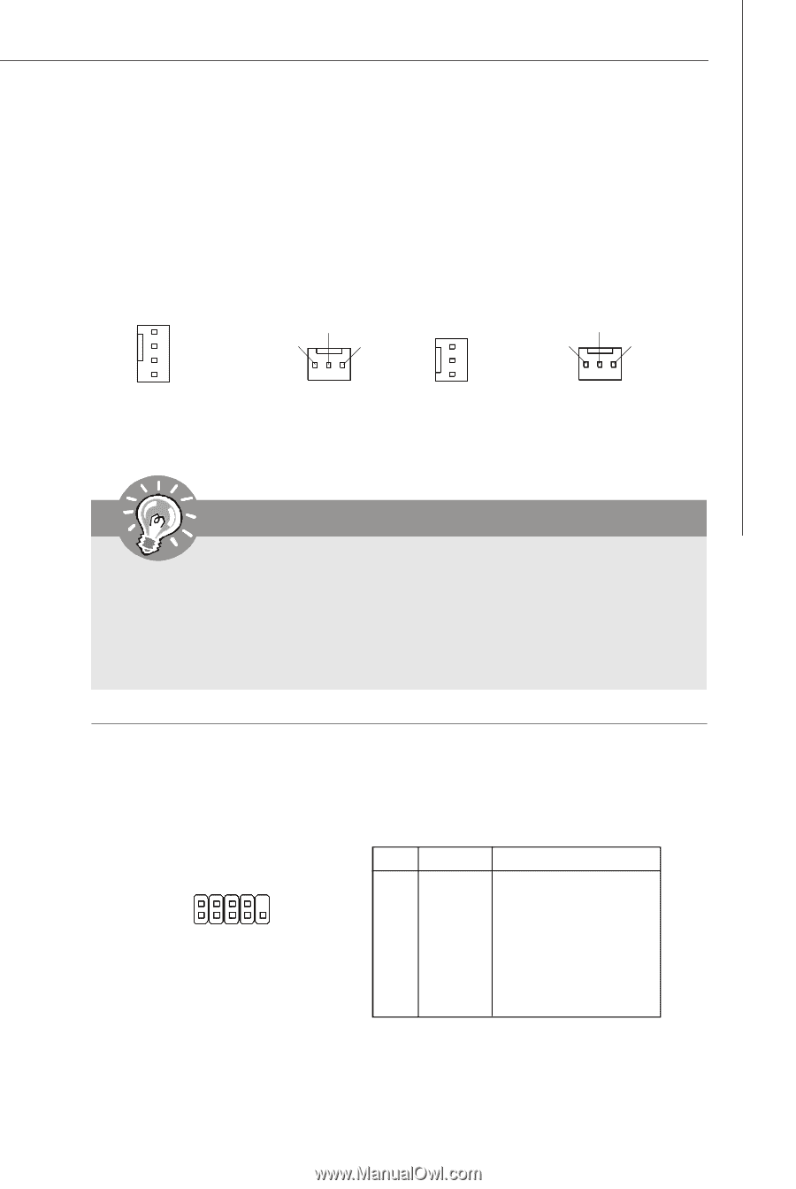
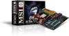
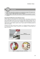
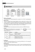
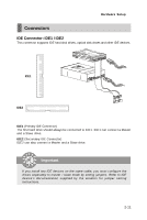
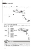
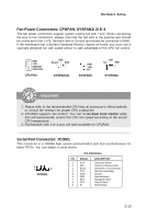
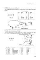
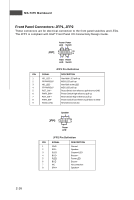
Hardware Setup Fan Power Connectors: CPUFAN, SYSFAN1/ 2/ 3/ 4 The fan power connectors support system cooling fan with +12V. W hen connecting the wire to the connectors, always note that the red wire is the positive and should be connected to the +12V; the black wire is Ground and should be connected to GND. If the mainboard has a System Hardware Monitor chipset on-board, you must use a specially designed fan with speed sensor to take advantage of the CPU fan control. GND +12V SENSOR CONTROL CPUFAN +12V Sensor GND SYSFAN1/2 GND +12V NC SYSFAN3 +12V NC GND SYSFAN4 Important 1. Please refer to the recommended CPU fans at processor's official website or consult the vendors for proper CPU cooling fan. 2. CPUFAN supports fan control. You can install Dual Core Center utility that will automatically control the CPU fan speed according to the actual CPU temperature. 3. Fan/heatsink with 3 or 4 pins are both available for CPUFAN. Serial Port Connector: JCOM1 This connector is a 16550A high speed communication port that sends/receives 16 bytes FIFOs. You can attach a serial device. Pin Definition 2 1 9 JCOM1 PIN SIGNAL 1 DCD 2 SIN 3 SOUT 4 DTR 5 GND 6 DSR 7 RTS 8 CTS 9 RI DESCRIPTION Data Carry Detect Serial In or Receive Data Serial Out or Transmit Data Data Terminal Ready Ground Data Set Ready Request To Send Clear To Send Ring Indicate 2-13
-
 1
1 -
2
-
3
-
4
-
5
-
6
-
7
-
8
-
9
-
10
-
11
-
12
-
13
-
14
-
15
-
16
-
17
-
18
-
19
-
20
-
21
-
 22
22 -
 23
23 -
 24
24 -
 25
25 -
 26
26 -
 27
27 -
 28
28 -
 29
29 -
 30
30 -
 31
31 -
 32
32 -
33
-
34
-
35
-
36
-
37
-
38
-
39
-
40
-
41
-
42
-
43
-
44
-
45
-
46
-
47
-
48
-
49
-
50
-
51
-
52
-
53
-
54
-
55
-
56
-
57
-
58
-
59
-
60
-
61
-
62
-
63
-
64
-
65
-
66
-
67
-
68
-
69
-
70
-
71
-
72
-
73
-
74
-
75
-
76
-
77
-
78
-
79
-
80
-
81
-
82
-
83
-
84
-
85
-
86
-
87
-
88
-
89
-
90
-
91
-
92
-
93
-
94
-
95
-
96
-
97
-
98
-
99
-
100
-
101
-
102
-
103
-
104
-
105
-
106
-
107
-
108
-
109
-
110
-
111
-
112
-
113
-
114
-
115
-
116
-
117
-
118
-
119
-
120
-
121
-
122
-
123
 |
 |