MSI MEG X570 UNIFY User Manual - Page 38
SATA1~4: SATA 6Gb/s Connectors, JFP1, JFP2: Front Panel Connectors, transmission otherwise.
 |
View all MSI MEG X570 UNIFY manuals
Add to My Manuals
Save this manual to your list of manuals |
Page 38 highlights
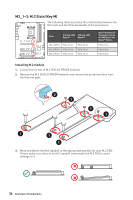
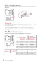
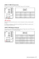
SATA1~4: SATA 6Gb/s Connectors These connectors are SATA 6Gb/s interface ports. Each connector can connect to one SATA device. SATA2 SATA1 SATA4 SATA3 Important yyPlease do not fold the SATA cable at a 90-degree angle. Data loss may result during transmission otherwise. yySATA cables have identical plugs on either sides of the cable. However, it is recommended that the flat connector be connected to the motherboard for space saving purposes. JFP1, JFP2: Front Panel Connectors These connectors connect to the switches and LEDs on the front panel. JFP1 1 3 5 7 9 Power Switch Power LED HDD LED + HDD LED Reset Switch Reset Switch Reserved ++ -- -+ - 10 9 21 2 4 6 8 10 + Reserved Reset Switch HDD LED Power LED + Power LED Power Switch Power Switch No Pin + - + Buzzer Speaker 1 Speaker - 2 1 JFP2 3 Buzzer - 4 Buzzer + Speaker + 38 Overview of Components
-
 1
1 -
2
-
3
-
4
-
5
-
6
-
7
-
8
-
9
-
10
-
11
-
12
-
13
-
14
-
15
-
16
-
17
-
18
-
19
-
20
-
21
-
22
-
23
-
24
-
25
-
26
-
27
-
28
-
29
-
30
-
31
-
32
-
 33
33 -
 34
34 -
 35
35 -
 36
36 -
 37
37 -
 38
38 -
 39
39 -
 40
40 -
 41
41 -
 42
42 -
 43
43 -
44
-
45
-
46
-
47
-
48
-
49
-
50
-
51
-
52
-
53
-
54
-
55
-
56
-
57
-
58
-
59
-
60
-
61
-
62
-
63
-
64
-
65
-
66
-
67
-
68
-
69
-
70
-
71
-
72
-
73
-
74
-
75
-
76
-
77
-
78
-
79
-
80
-
81
-
82
-
83
-
84
-
85
-
86
-
87
-
88
-
89
 |
 |
