MSI MEG X570 UNIFY User Manual - Page 48
Onboard LEDs, EZ Debug LED, JPWRLED1: LED power input, Debug Code LED
 |
View all MSI MEG X570 UNIFY manuals
Add to My Manuals
Save this manual to your list of manuals |
Page 48 highlights
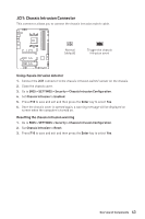
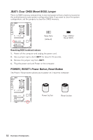
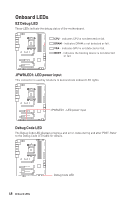
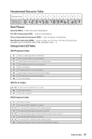
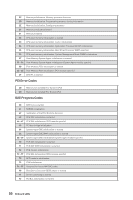
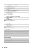
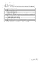
Onboard LEDs EZ Debug LED These LEDs indicate the debug status of the motherboard. CPU - indicates CPU is not detected or fail. DRAM - indicates DRAM is not detected or fail. VGA - indicates GPU is not detected or fail. BOOT - indicates the booting device is not detected or fail. JPWRLED1: LED power input This connector is used by retailers to demonstrate onboard LED lights. JPWRLED1 - LED power input Debug Code LED The Debug Code LED displays progress and error codes during and after POST. Refer to the Debug Code LED table for details. 48 Onboard LEDs Debug Code LED
-
 1
1 -
2
-
3
-
4
-
5
-
6
-
7
-
8
-
9
-
10
-
11
-
12
-
13
-
14
-
15
-
16
-
17
-
18
-
19
-
20
-
21
-
22
-
23
-
24
-
25
-
26
-
27
-
28
-
29
-
30
-
31
-
32
-
33
-
34
-
35
-
36
-
37
-
38
-
39
-
40
-
41
-
42
-
 43
43 -
 44
44 -
 45
45 -
 46
46 -
 47
47 -
 48
48 -
 49
49 -
 50
50 -
 51
51 -
 52
52 -
 53
53 -
54
-
55
-
56
-
57
-
58
-
59
-
60
-
61
-
62
-
63
-
64
-
65
-
66
-
67
-
68
-
69
-
70
-
71
-
72
-
73
-
74
-
75
-
76
-
77
-
78
-
79
-
80
-
81
-
82
-
83
-
84
-
85
-
86
-
87
-
88
-
89
 |
 |

48
Onboard LEDs
EZ Debug LED
These LEDs indicate the debug status of the motherboard.
CPU
- indicates CPU is not detected or fail.
DRAM
- indicates DRAM is not detected or fail.
VGA
- indicates GPU is not detected or fail.
BOOT
- indicates the booting device is not detected
or fail.
Onboard LEDs
JPWRLED1: LED power input
This connector is used by retailers to demonstrate onboard LED lights.
JPWRLED1 - LED power input
Debug Code LED
Debug Code LED
The Debug Code LED displays progress and error codes during and after POST. Refer
to the Debug Code LED table for details.