MSI MEG X570 UNIFY User Manual - Page 40
JUSB1: USB 3.2 Gen 2 Type-C Connector, JUSB2~3: USB 3.2 Gen1 Connector, USB Type-C Cable
 |
View all MSI MEG X570 UNIFY manuals
Add to My Manuals
Save this manual to your list of manuals |
Page 40 highlights
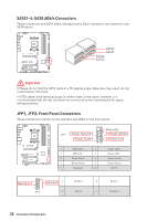
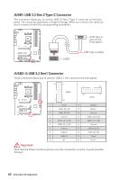
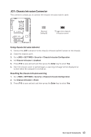
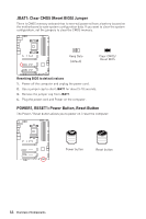
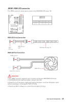
JUSB1: USB 3.2 Gen 2 Type-C Connector This connector allows you to connect USB 3.2 Gen 2 Type-C connector on the front panel. The connector possesses a foolproof design. When you connect the cable, be sure to connect it with the corresponding orientation. JUSB1 USB Type-C port on the front panel USB Type-C Cable JUSB2~3: USB 3.2 Gen1 Connector These connectors allow you to connect USB 3.2 Gen1 ports on the front panel. 10 11 1 10 JUSB3 1 20 20 11 JUSB2 1 Power 11 2 USB3_RX_DN 12 3 USB3_RX_DP 13 4 Ground 14 5 USB3_TX_C_DN 15 6 USB3_TX_C_DP 16 7 Ground 17 8 USB2.0- 18 9 USB2.0+ 19 10 NC 20 USB2.0+ USB2.0Ground USB3_TX_C_DP USB3_TX_C_DN Ground USB3_RX_DP USB3_RX_DN Power No Pin Important Note that the Power and Ground pins must be connected correctly to avoid possible damage. 40 Overview of Components
-
 1
1 -
2
-
3
-
4
-
5
-
6
-
7
-
8
-
9
-
10
-
11
-
12
-
13
-
14
-
15
-
16
-
17
-
18
-
19
-
20
-
21
-
22
-
23
-
24
-
25
-
26
-
27
-
28
-
29
-
30
-
31
-
32
-
33
-
34
-
 35
35 -
 36
36 -
 37
37 -
 38
38 -
 39
39 -
 40
40 -
 41
41 -
 42
42 -
 43
43 -
 44
44 -
 45
45 -
46
-
47
-
48
-
49
-
50
-
51
-
52
-
53
-
54
-
55
-
56
-
57
-
58
-
59
-
60
-
61
-
62
-
63
-
64
-
65
-
66
-
67
-
68
-
69
-
70
-
71
-
72
-
73
-
74
-
75
-
76
-
77
-
78
-
79
-
80
-
81
-
82
-
83
-
84
-
85
-
86
-
87
-
88
-
89
 |
 |
