MSI MEG X570S UNIFY-X MAX User Manual - Page 19
Internal Connectors, Buttons, Jumpers, LED Features, I/O Controller
 |
View all MSI MEG X570S UNIFY-X MAX manuals
Add to My Manuals
Save this manual to your list of manuals |
Page 19 highlights
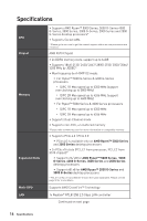
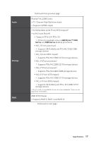
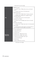
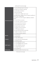
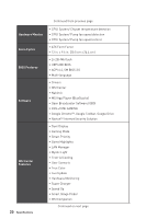
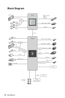
Continued from previous page Internal Connectors Buttons Jumpers LED Features ∙∙1x 24-pin ATX main power connector ∙∙2x 8-pin ATX 12V power connector ∙∙6x SATA 6Gb/s connectors ∙∙6x M.2 slots (M-Key) ∙∙1x USB 3.2 Gen 2 10Gbps Type-C port ∙∙2x USB 3.2 Gen 1 5Gbps connector (supports additional 4 USB 3.2 Gen 1 5Gbps ports) ∙∙2x USB 2.0 connectors (supports additional 4 USB 2.0 ports) ∙∙1x 4-pin CPU fan connector ∙∙1x 4-pin water-pump fan connector ∙∙6x 4-pin system fan connectors ∙∙1x Front panel audio connector ∙∙2x System panel connectors ∙∙1x Chassis Intrusion connector ∙∙1x TPM module connector ∙∙2x 2-pin Thermal Sensors connectors ∙∙1x Water Flow Meter connector ∙∙1x Tuning Controller connector ∙∙1x Power button ∙∙1x Reset button ∙∙1x Clear CMOS jumper ∙∙1x Low temperature booting jumper ∙∙1x Safe Boot jumper ∙∙1x 4-pin RGB LED connector ∙∙2x 3-pin RAINBOW LED connectors ∙∙1x 3-pin CORSAIR connector ∙∙1x 2-Digit Debug Code LED ∙∙4x EZ Debug LED I/O Controller NUVOTON NCT6687D-R Controller Chip Continued on next page Specifications 19
-
 1
1 -
2
-
3
-
4
-
5
-
6
-
7
-
8
-
9
-
10
-
11
-
12
-
13
-
 14
14 -
 15
15 -
 16
16 -
 17
17 -
 18
18 -
 19
19 -
 20
20 -
 21
21 -
 22
22 -
 23
23 -
 24
24 -
25
-
26
-
27
-
28
-
29
-
30
-
31
-
32
-
33
-
34
-
35
-
36
-
37
-
38
-
39
-
40
-
41
-
42
-
43
-
44
-
45
-
46
-
47
-
48
-
49
-
50
-
51
-
52
-
53
-
54
-
55
-
56
-
57
-
58
-
59
-
60
-
61
-
62
-
63
-
64
-
65
-
66
-
67
-
68
 |
 |