MSI MEG Z690 UNIFY-X User Manual
MSI MEG Z690 UNIFY-X Manual
 |
View all MSI MEG Z690 UNIFY-X manuals
Add to My Manuals
Save this manual to your list of manuals |
MSI MEG Z690 UNIFY-X manual content summary:
- MSI MEG Z690 UNIFY-X | User Manual - Page 1
Quick Start Thank you for purchasing the MSI® MEG Z690 UNIFY-X motherboard. This Quick Start section provides demonstration diagrams about how to install your computer. Some of the installations also provide video demonstrations. Please link to - MSI MEG Z690 UNIFY-X | User Manual - Page 2
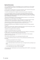
Please adhere to the following instructions to ensure successful computer following situations arises, get the motherboard checked by service personnel: ▪▪Liquid has penetrated into the computer. you can not get it work according to user guide. ▪▪The motherboard has been dropped and damaged. - MSI MEG Z690 UNIFY-X | User Manual - Page 3
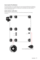
Case stand-off notification To prevent damage to the motherboard, any unnecessary mounting stand-off between the motherboard circuits and the computer case is prohibited. The Case standoff keep out zone signs will be marked on the backside of motherboard (as shown below) to serve as a warning to - MSI MEG Z690 UNIFY-X | User Manual - Page 4
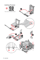
Installing a Processor ⚽ ⚽ 1 https://youtu.be/KMf9oIDsGes 2 3 7 5 4 9 6 8 4 Quick Start - MSI MEG Z690 UNIFY-X | User Manual - Page 5
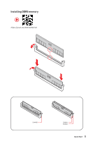
Installing DDR5 memory ⚽ ⚽ https://youtu.be/XiNmkDNZcZk DIMMB1 DIMMA1 DIMMB1 Quick Start 5 - MSI MEG Z690 UNIFY-X | User Manual - Page 6
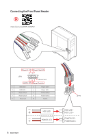
Connecting the Front Panel Header ⚽ ⚽ http://youtu.be/DPELIdVNZUI POPWOEWRELREHLDD-EDDL+ED RESET SW POWER SW Power LED Power Switch - -+ -- ++ JFP1 2 1 + 10 9 Reserved HDD LED Reset Switch 1 HDD LED + 2 3 HDD LED - 4 5 Reset Switch 6 7 Reset Switch 8 9 Reserved 10 Power - MSI MEG Z690 UNIFY-X | User Manual - Page 7
Installing the Motherboard 1 ⚽ ⚽ https://youtu.be/wWI6Qt51Wnc Torque: 3 kgf·cm* 2 *3 kgf·cm = 0.3 N·m = 2.6 lbf·in Quick Start 7 - MSI MEG Z690 UNIFY-X | User Manual - Page 8
Connecting the Power Connectors ⚽ ⚽ http://youtu.be/gkDYyR_83I4 ATX_PWR1 8 Quick Start CPU_PWR1 CPU_PWR2 - MSI MEG Z690 UNIFY-X | User Manual - Page 9
Installing SATA Drives ⚽ ⚽ http://youtu.be/RZsMpqxythc 2 1 3 5 4 Quick Start 9 - MSI MEG Z690 UNIFY-X | User Manual - Page 10
Installing a Graphics Card ⚽ ⚽ http://youtu.be/mG0GZpr9w_A 1 3 2 5 10 Quick Start 4 6 - MSI MEG Z690 UNIFY-X | User Manual - Page 11
Connecting Peripheral Devices Quick Start 11 - MSI MEG Z690 UNIFY-X | User Manual - Page 12
Power On 1 2 3 4 12 Quick Start - MSI MEG Z690 UNIFY-X | User Manual - Page 13
Contents Quick Start...1 Preparing Tools and Components 1 Safety Information 2 Case stand-off notification 3 Avoid collision notification 3 Installing a Processor 4 Installing DDR5 memory 5 Connecting the Front Panel Header 6 Installing the Motherboard 7 Connecting the Power Connectors 8 - MSI MEG Z690 UNIFY-X | User Manual - Page 14
OS, Drivers & MSI Center 62 Installing Windows® 10 62 Installing Drivers 62 MSI Center...62 UEFI BIOS...63 BIOS Setup...64 Entering BIOS Setup 64 BIOS User Guide...64 Resetting BIOS...65 Updating BIOS...65 RAID Configuration 67 Intel® Optane™ Memory Configuration 68 Troubleshooting 69 14 - MSI MEG Z690 UNIFY-X | User Manual - Page 15
® Gold and Celeron® Processors* ∙∙Processor socket LGA1700 * Please go to www.msi.com to get the newest support status as new processors are released. Intel® Z690 Chipset ∙∙2x DDR5 memory slots, support up to 64GB* ∙∙Supports 1R 4800 MHz (by JEDEC & POR) ∙∙Max. overclocking frequency: ▪▪1DPC 1R - MSI MEG Z690 UNIFY-X | User Manual - Page 16
▪▪M2_2 slot (From Z690 Chipset) ▫▫Supports PCIe 4.0 x4 ▫▫Supports 2260/ 2280 storage devices ▪▪M2_3 slot (From Z690 Chipset) ▫▫Supports PCIe 4.0x4 ▫▫Supports SATA 6Gb/s ▫▫Supports 2260/ 2280/ 22110 storage devices ▪▪M2_4 slot (From Z690 Chipset) ▫▫Supports PCIe 3.0x4 ▫▫Supports 2260/ 2280 storage - MSI MEG Z690 UNIFY-X | User Manual - Page 17
/s connectors ∙∙5x M.2 slots (M-Key) ∙∙1x USB 3.2 Gen 2x2 20Gbps Type-C port ∙∙2x USB 3.2 Gen 1 5Gbps connector (supports additional 4 USB 3.2 Gen 1 5Gbps ports) ∙∙2x USB 2.0 connectors (supports additional 4 USB 2.0 ports) ∙∙1x 4-pin CPU fan connector ∙∙1x 4-pin water-pump fan connector ∙∙6x 4-pin - MSI MEG Z690 UNIFY-X | User Manual - Page 18
Continued from previous page Jumpers LED Features Back Panel Connectors I/O Controller Hardware Monitor Form Factor ∙∙1x Clear CMOS jumper ∙∙1x Slow mode jumper ∙∙2x Low temperature booting jumpers ∙∙1x Safe boot jumper ∙∙1x OC Retry jumper ∙∙1x 2-Digit Debug Code LED ∙∙4x EZ Debug LED ∙∙1x 4-pin - MSI MEG Z690 UNIFY-X | User Manual - Page 19
Mb flash ∙∙UEFI AMI BIOS ∙∙ACPI 6.2, SMBIOS 3.0 ∙∙ Multi-language ∙∙ Drivers ∙∙MSI Center ∙∙Intel Extreme Tuning Utility ∙∙ Nahimic ∙∙MSI APP Player (Bluestack) ∙∙Open Broadcaster Software (OBS) ∙∙CPU-Z MSI GAMING ∙∙Google Chrome™, Google Toolbar, Google Drive ∙∙Norton™ Internet Security Solution - MSI MEG Z690 UNIFY-X | User Manual - Page 20
Special Features Continued from previous page ∙∙ Audio ▪▪Audio Boost 5 ▪▪Nahimic 3 ▪▪Sound Tune ∙∙ Network ▪▪2.5G LAN ▪▪LAN Manager ▪▪Intel WiFi ∙∙ Cooling ▪▪All Aluminum Design ▪▪Heat-pipe Design ▪▪Extended Heatsink Design ▪▪Aluminum Backplate ▪▪M.2 Shield Frozr ▪▪Pump Fan ▪▪K7 thermal pad ▪▪Choke - MSI MEG Z690 UNIFY-X | User Manual - Page 21
▪▪Front USB Type-C ▪▪Dual CPU Power ▪▪Server PCB ▪▪2oz Copper thickened PCB ∙∙ Protection ▪▪PCI-E Steel Armor ▪▪Pre-installed I/O Shield ∙∙ Experience ▪▪Smart Button ▪▪MSI Center ▪▪Frozr AI Cooling ▪▪Click BIOS 5 ▪▪System Saver ▪▪Flash BIOS Button ▪▪EZ M.2 Clip ▪▪App Player ▪▪Tile Specifications 21 - MSI MEG Z690 UNIFY-X | User Manual - Page 22
Package contents Please check the contents of your motherboard package. It should contain: Motherboard MEG Z690 UNIFY-X User manual 1 Documentation Quick installation guide 1 Application USB drive with drivers & utilities 1 SATA 6Gb/s cables 2 LED JRGB Y cable 1 LED JCORSAIR cable 1 - MSI MEG Z690 UNIFY-X | User Manual - Page 23
Block Diagram PCI_E1 PCIe x16 CPU PCI_E2 PCIe x8 M2_1 PCI_E3 PCIe 3.0 x4 M2_2, M2_3, M2_4, M2_5 SATA5/6/7/8 SATAA/B Intel LAN ASM1061 Intel Wi-Fi DDR5 DIMM A1 DIMM B1 DMI x8 PCH USB3.2 Gen2x2 20Gbps USB 3.2 Gen 2 10Gbps GL3590OTY10 USB 3.2 Gen 2 10Gbps ASM USB 3.2 Gen 1 5Gbps 1074 USB - MSI MEG Z690 UNIFY-X | User Manual - Page 24
Rear I/O Panel Clear CMOS PS/2 button 2.5Gbps LAN Audio Ports USB 2.0 Type A USB 3.2 Gen 2 10Gbps Type A Flash BIOS Flash BIOS USB 3.2 Gen 2x2 Button port (20Gbps) Type-C Optical S/PDIF-Out Wi-Fi Antenna connectors ∙∙ Flash BIOS Port/ Button - Please refer to page 66 for Updating BIOS with - MSI MEG Z690 UNIFY-X | User Manual - Page 25
Realtek Audio Console After Realtek Audio Console is installed. You can use it to change sound settings to get better sound experience. Application Enhancement Device Selection Main Volume Connector Settings Jack Status ∙∙ Device Selection - allows you to select a audio output source to change - MSI MEG Z690 UNIFY-X | User Manual - Page 26
Audio jacks to headphone and microphone diagram Audio jacks to stereo speakers diagram AUDIO INPUT Audio jacks to 7.1-channel speakers diagram AUDIO INPUT Rear Front Side Center/ Subwoofer 26 Rear I/O Panel - MSI MEG Z690 UNIFY-X | User Manual - Page 27
Installing Antennas 1. Combine the antenna with the base. 2. Screw two antenna cables tight to the WiFi antenna connectors as shown. 2 1 3. Place the antenna as high as possible. Rear I/O Panel 27 - MSI MEG Z690 UNIFY-X | User Manual - Page 28
Overview of Components Processor Socket CPU_PWR2 CPU_PWR1 DIMMB1 DIMMA1 CPU_FAN1 PUMP_FAN1 SYS_FAN1 SYS_FAN6 SYS_FAN5 JRAINBOW2 JCORSAIR1 T_SEN1 ATX_PWR1 M2_1 PCI_E1 M2_2 M2_3 PCI_E2 JLN1,JLN2,JCI1 M2_4 PCI_E3 JUSB5 JUSB3 M2_5 JUSB4 SATA▼5▲6 SATA▼7▲8 SYS_ POWER1 FAN3 RESET1 JAUD1 - MSI MEG Z690 UNIFY-X | User Manual - Page 29
Component Contents Port Name BIOS_SW1 CPU_FAN1, PUMP_FAN1, SYS_FAN1~6 CPU_PWR1~2, ATX_PWR1 CPU Socket DIMM Slots JAUD1 JBAT1 JCI1 JCORSAIR1 JDASH1 JFP1, JFP2 JLN1~2 JOC_FS1 JOC_RT1 JRAINBOW1~2 JRGB1 JSLOW1 JTBT1 JTPM1 JUSB1~2 JUSB3~4 JUSB5 M2_1~5 PCI_E1~3 POWER1, RESET1 SATA5~8 & SATAA~B1 T_SEN1~2 - MSI MEG Z690 UNIFY-X | User Manual - Page 30
CPU. ∙∙Please retain the CPU protective cap after installing the processor. MSI will deal with Return Merchandise Authorization (RMA) requests if only the more details about installation. ∙∙This motherboard is designed to support overclocking. Before attempting to overclock, please make sure that - MSI MEG Z690 UNIFY-X | User Manual - Page 31
full DIMMs installation or overclocking. ∙∙The stability and compatibility of installed memory module depend on installed CPU and devices when overclocking. ∙∙Please refer to www.msi.com for more information on compatible memory. Overview of Components 31 - MSI MEG Z690 UNIFY-X | User Manual - Page 32
3.0 x4 (From Z690 Chipset) ⚠⚠Important ∙∙If you install a large and heavy graphics card, you need to use a tool such as MSI Graphics Card Bolster to support its weight to supply recommendations for SLI configurations, Please refer to the user guide of your graphics card to make sure you meet all - MSI MEG Z690 UNIFY-X | User Manual - Page 33
3. Connect all PCIe power connectors of the graphics cards. 4. Reconnect the power cord, power up the computer and install the drivers and software included in your graphics card package. 5. Right-click the Windows desktop and select NVIDIA Control Panel from the menu, click on Configure SLI, - MSI MEG Z690 UNIFY-X | User Manual - Page 34
M2_1~5: M.2 Slots (Key M) ⚠⚠Important ∙∙Intel® RST only supports PCIe M.2 SSD with UEFI ROM. ∙∙Intel® Optane™ Memory Ready for M2_2~5 M2_1 slots. M2_2 M2_3 M2_5 M2_4 M2_1, M2_2 slots Installation 1. Loosen the screws of M.2 - MSI MEG Z690 UNIFY-X | User Manual - Page 35
4. If you install 2260 SSD, remove the screw from the M.2 plate and then install supplied EZ M.2 Clip kit on the M.2 plate. Skip this step, if you install 2280 SSD. 4 2260 SSD 5. Insert your M.2 SSD into the M.2 slot at a 30-degree angle. 6. Rotate the EZ M.2 Clip to fix the M.2 SSD. 5 6 30º 5 - MSI MEG Z690 UNIFY-X | User Manual - Page 36
M2_3 slot Installation 1. Loosen the screws of M.2 SHIELD FROZR heatsink. 2. Remove the M.2 SHIELD FROZR and remove the protective films from the thermal pads. 1 1 2 3. Remove the protective films from the M.2 thermal pads on the M.2 plate. 3 4. Remove or exchange the screws according to your SSD - MSI MEG Z690 UNIFY-X | User Manual - Page 37
5 6 30º 22110 SSD 5 30º 2280 SSD 2260 SSD 6 7. Put the M.2 SHIELD FROZR heatsink back in place and secure it. Overview of Components 37 - MSI MEG Z690 UNIFY-X | User Manual - Page 38
M2_4, M2_5 slots installation 1. Loosen the screws of M.2 SHIELD FROZR heatsink. 2. Remove the M.2 SHIELD FROZR and remove the protective films from the thermal pads. 1 2 1 3. Remove the protective films from the M.2 thermal pads on the M.2 plate. 3 38 Overview of Components - MSI MEG Z690 UNIFY-X | User Manual - Page 39
4. If there is a screw installed on the M.2 plate, remove it first; otherwise, please skip this step. 5. Secure the supplied M.2 standoff according to your M.2 SSD length. Standoff 5 4 6. Insert your M.2 SSD into the M.2 slot at a 30-degree angle. 7. Secure the M.2 SSD in place with the supplied - MSI MEG Z690 UNIFY-X | User Manual - Page 40
8. Put the M.2 SHIELD FROZR heatsink back in place and secure it. 8 8 SATA5~8 & SATAA~B1: SATA 6Gb/s Connectors These connectors are SATA 6Gb/s interface ports. Each connector can connect to one SATA device. SATA6 SATA5 SATA8 SATA7 SATAB1 SATAA ⚠⚠Important ∙∙Please do not fold the SATA cable at a 90 - MSI MEG Z690 UNIFY-X | User Manual - Page 41
CPU_PWR1~2, ATX_PWR1: Power Connectors These connectors allow you to connect an ATX power supply. 8 5 CPU_PWR1~2 4 1 1 Ground 5 2 Ground 6 3 Ground 7 4 Ground 8 +12V +12V +12V +12V 1 +3.3V 13 2 +3.3V 14 3 Ground 15 12 24 4 +5V 16 5 Ground 17 6 +5V 18 ATX_PWR1 7 - MSI MEG Z690 UNIFY-X | User Manual - Page 42
JSLOW1: Slow Mode Booting Jumper This jumper is used for LN2 cooling solution, that provides the extreme overclocking conditions, to boot at a stable processor frequency and to prevent the system from crashing. Normal (Default) Enabled (Please enable this jumper during BIOS POST.) JLN1~2: Low - MSI MEG Z690 UNIFY-X | User Manual - Page 43
control and overclock the motherboard more easily. Please follow the instructions below to understand the function of each button on the error codes during and after POST. Please refer to the Debug Code LED table in this manual for details. ∙∙ OC button- / + - these buttons are used to decrease/ - MSI MEG Z690 UNIFY-X | User Manual - Page 44
you to stick it to the chassis. However, we provide extra four magnets for sticking inside the back cover of module. Please follow the instructions below to stick the magnets. 1. Loosen the screws of the back cover. 2. Open and turn the back cover over. 1 1 2 1 1 3. Remove the sticker from the - MSI MEG Z690 UNIFY-X | User Manual - Page 45
JOC_FS1: Safe Boot Jumper This jumper is used for Safe Boot. Once enabled, the system will boot with default settings and lower PCIe (from CPU) mode. Normal (default) Boot with the saved BIOS settings. Enabled Apply the BIOS default settings and lower PCIe (from CPU) mode for Safe Boot JOC_RT1: - MSI MEG Z690 UNIFY-X | User Manual - Page 46
JAUD1: Front Audio Connector This connector allows you to connect audio jacks on the front panel. 2 10 1 9 1 MIC L 2 Ground 3 MIC R 4 NC 5 Head Phone R 6 MIC Detection 7 SENSE_SEND 8 No Pin 9 Head Phone L 10 Head Phone Detection JTBT1: Thunderbolt Add-on Card Connector This - MSI MEG Z690 UNIFY-X | User Manual - Page 47
JUSB5: USB 3.2 Gen 2x2 Type-C Connector This connector allows you to connect USB 3.2 Gen 2x2 Type-C connector on the front panel. The connector possesses a foolproof design. When you connect the cable, be sure to connect it with the corresponding orientation. JUSB5 USB Type-C Cable USB Type-C - MSI MEG Z690 UNIFY-X | User Manual - Page 48
recharge your iPad, iPhone and iPod through USB ports, please install MSI® Center utility. JTPM1: TPM Module Connector This connector is for TPM (Trusted Platform Module). Please refer to the TPM security platform manual for more details and usages. 2 12 1 11 1 SPI Power 2 3 - MSI MEG Z690 UNIFY-X | User Manual - Page 49
The auto mode fan connectors can automatically detect PWM and DC mode. However, you can follow the instruction below to adjust the fan connector to PWM or DC Mode manually. CPU_FAN1 PUMP_FAN1 SYS_FAN1 SYS_FAN6 SYS_FAN5 Connector CPU_FAN1 PUMP_FAN1 SYS_FAN1~6 Default fan mode Auto mode PWM mode DC - MSI MEG Z690 UNIFY-X | User Manual - Page 50
be required to check voltages. To measure voltage, place test leads on the GND (screw mounting hole) and a specific V-Check Point. Please refer to the manual of your multimeter for more information. GND CPU_AUX CPUVDD2 VCC SOCKET 50 Overview of Components - MSI MEG Z690 UNIFY-X | User Manual - Page 51
JCI1: Chassis Intrusion Connector This connector allows you to connect the chassis intrusion switch cable. Normal (default) Trigger the chassis intrusion event Using chassis intrusion detector 1. Connect the JCI1 connector to the chassis intrusion switch/ sensor on the chassis. 2. Close the - MSI MEG Z690 UNIFY-X | User Manual - Page 52
(Red: BIOS B, White: BIOS A) BIOS B BIOS A (Default) ⚠⚠Important ∙∙Do not use the Multi-BIOS switch when system is booting up. ∙∙You can also use the MSI Center or Flash BIOS Button to flash BIOS. Please refer to BIOS section for details. 52 Overview of Components - MSI MEG Z690 UNIFY-X | User Manual - Page 53
LED strips 12V GR B 1 System Fan connector RGB LED Fan ⚠⚠Important ∙∙The JRGB connector supports up to 2 meters continuous 5050 RGB LED strips (12V/G/R/B) with the maximum power rating of the RGB LED strip. ∙∙Please use MSI's software to control the extended LED strip. Overview of Components 53 - MSI MEG Z690 UNIFY-X | User Manual - Page 54
result in damage to the LED strip. ⚠⚠Important ∙∙The JRAINBOW connector supports up to 75 LEDs WS2812B Individually Addressable RGB LED strips (5V/Data/Ground rating of 3A (5V). In the case of 20% brightness, the connector supports up to 200 LEDs. ∙∙Always turn off the power supply and unplug the - MSI MEG Z690 UNIFY-X | User Manual - Page 55
connected properly, you can control the CORSAIR RGB LED strips and fans with MSI's software. 1 1 +5V 2 3 Ground Data CORSAIR RGB LED fan CORSAIR ∙∙Quantity of RGB LED Fans or RGB LED Lighting PRO strips supported may differ between models. Please refer to the motherboard specification. ∙∙ - MSI MEG Z690 UNIFY-X | User Manual - Page 56
Onboard LEDs EZ Debug LED These LEDs indicate the debug status of the motherboard. CPU - indicates CPU is not detected or fail. DRAM - indicates DRAM is not detected or fail. VGA - indicates GPU is not detected or fail. BOOT - indicates the booting device is not detected or fail. Debug Code LED The - MSI MEG Z690 UNIFY-X | User Manual - Page 57
Debug Code LED Table SEC Progress Codes 01 Power on. Reset type detection (soft/hard) 02 AP initialization before microcode loading 03 System Agent initialization before microcode loading 04 PCH initialization before microcode loading 06 Microcode loading 07 AP initialization after - MSI MEG Z690 UNIFY-X | User Manual - Page 58
Reserved for future AMI error codes DXE Progress Codes 60 DXE Core is started 61 NVRAM initialization 62 Installation of the PCH Runtime Services 63 CPU DXE initialization is started 64 - 67 CPU DXE initialization (CPU module specific) 68 PCI host bridge initialization 69 System Agent - MSI MEG Z690 UNIFY-X | User Manual - Page 59
started SCSI Reset SCSI Detect SCSI Enable Setup Verifying Password Start of Setup Setup Input Wait Ready To Boot event Legacy Boot event Exit Boot Services event Runtime Set Virtual Address MAP Begin Onboard LEDs 59 - MSI MEG Z690 UNIFY-X | User Manual - Page 60
B1 Runtime Set Virtual Address MAP End B2 Legacy Option ROM Initialization B3 System Reset B4 USB hot plug B5 PCI bus hot plug B6 Clean-up of NVRAM B7 Configuration Reset (reset of NVRAM settings) B8 - BF Reserved for future AMI codes DXE Error Codes D0 CPU initialization error D1 - MSI MEG Z690 UNIFY-X | User Manual - Page 61
EA EB EC - EF S3 Resume Boot Script Error S3 OS Wake Error Reserved for future AMI error codes Recovery Progress Codes F0 Recovery condition triggered by firmware (Auto recovery) F1 Recovery condition triggered by user (Forced recovery) F2 Recovery process started F3 Recovery firmware - MSI MEG Z690 UNIFY-X | User Manual - Page 62
. 7. Follow the instructions on the screen to install Windows® 10. Installing Drivers 1. Start up your computer in Windows® 10. 2. Insert MSI® USB Drive into speed. MSI Center User Guide If you would like to know more information about MSI Center, please refer to http://download.msi.com/manual/mb - MSI MEG Z690 UNIFY-X | User Manual - Page 63
the time to switch to CSM mode during POST. ∙∙Supports for hard drive partitions larger than 2 TB. ∙∙Supports more than 4 primary partitions with a GUID Partition Table (GPT). ∙∙Supports unlimited number of partitions. ∙∙Supports full capabilities of new devices - new devices may not provide - MSI MEG Z690 UNIFY-X | User Manual - Page 64
window appears and it provides the modification information. Select between Yes or No to confirm your choice. BIOS User Guide If you'd like to know more instructions on setting up the BIOS, please refer to http://download.msi.com/manual/mb/Intel600BIOS.pdf or scan the QR code to access. 64 UEFI BIOS - MSI MEG Z690 UNIFY-X | User Manual - Page 65
need to restore the default BIOS setting to solve certain problems. There are several ways to reset BIOS: ∙∙Go to FLASH Before updating: Please download the latest BIOS file that matches your motherboard model from MSI website. And then save the BIOS file into the USB flash drive. Updating BIOS: - MSI MEG Z690 UNIFY-X | User Manual - Page 66
updating the BIOS. To update BIOS: 1. Install and launch MSI Center and go to Support page. 2. Select Live Update and click on Advance button need to install CPU and memory.) 4. Plug the USB storage device that contains the MSI.ROM file into the Flash BIOS Port on the rear I/O panel. 5. Press the - MSI MEG Z690 UNIFY-X | User Manual - Page 67
/ pictures listed in your system might differ from the illustrations in this appendix. Intel RAID User Guide If you'd like to know more instructions on how to set up Intel RAID, please refer to http://download.msi.com/manual/mb/IntelRAID600.pdf or scan the QR code to access. RAID Configuration 67 - MSI MEG Z690 UNIFY-X | User Manual - Page 68
® Optane™ Memory User Guide If you'd like to know more instructions on how to enable or remove Intel® Optane™ Memory, please refer to http://download.msi.com/manual/mb/Optane600.pdf or scan DO NOT replace the CPU that is not supported by Intel® Optane™ Memory. 68 Intel® Optane™ Memory Configuration - MSI MEG Z690 UNIFY-X | User Manual - Page 69
Before sending the motherboard for RMA repair, try to go over troubleshooting guide first to see if your got similar symptoms as mentioned below. The power is not on. ∙∙Connect ∙∙Clear the CMOS. ∙∙Use the secondary BIOS to bootup the system (Only for motherboard with Dual BIOS) Troubleshooting 69 - MSI MEG Z690 UNIFY-X | User Manual - Page 70
energy and, if not installed and used in accordance with the instructions, may cause harmful interference to radio communications. However, there is regulatory matters is MSI, MSI-NL Eindhoven 5706 5692 ER Son. KC인증서 yy MEG Z690 UNIFY-X R-R-MSI-20-7D28 20-7D28 2021 MSI/중국 クラスB VCCI-B - MSI MEG Z690 UNIFY-X | User Manual - Page 71
la communauté européenne. Par conséquent vous pouvez retourner localement ces matériels dans les points de collecte. MSI WEEE 2002/96/EC 13 2005 MSI MSI EC ESPAÑOL MSI como empresa comprometida con la protección del medio ambiente, recomienda: Bajo la directiva 2002/96/EC de la Uni - MSI MEG Z690 UNIFY-X | User Manual - Page 72
ben, hogy környezetünket megvédjük, illetve környezetvédőként fellépve az MSI emlékezteti Önt, hogy ... Az Európai Unió („EU") 2005 unless otherwise indicated in instructions specific to the product. lead to interference issues with existing radio services. Radio frequency bands and maximum power - MSI MEG Z690 UNIFY-X | User Manual - Page 73
PBDE Copyright Micro-Star Int'l Co.,Ltd. Copyright © 2021 All rights reserved. The MSI logo used is a registered trademark of Micro-Star Int'l Co., Ltd. All other release. Technical Support If a problem arises with your system and no solution can be obtained from the user guide, please contact
-
 1
1 -
 2
2 -
 3
3 -
 4
4 -
 5
5 -
 6
6 -
 7
7 -
8
-
9
-
10
-
11
-
12
-
13
-
14
-
15
-
16
-
17
-
18
-
19
-
20
-
21
-
22
-
23
-
24
-
25
-
26
-
27
-
28
-
29
-
30
-
31
-
32
-
33
-
34
-
35
-
36
-
37
-
38
-
39
-
40
-
41
-
42
-
43
-
44
-
45
-
46
-
47
-
48
-
49
-
50
-
51
-
52
-
53
-
54
-
55
-
56
-
57
-
58
-
59
-
60
-
61
-
62
-
63
-
64
-
65
-
66
-
67
-
68
-
69
-
70
-
71
-
72
-
73
 |
 |
1
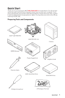
Quick Start
Quick Start
Thank you for purchasing the MSI®
MEG Z690 UNIFY-X
motherboard. This Quick Start
section provides demonstration diagrams about how to install your computer. Some
of the installations also provide video demonstrations. Please link to the URL to watch
it with the web browser on your phone or tablet. You may have even link to the URL by
scanning the QR code.
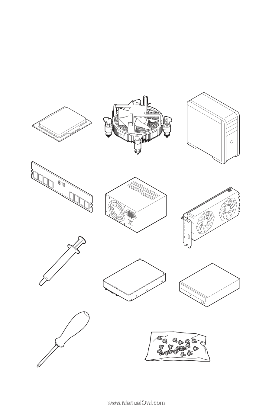
Preparing Tools and Components
Intel® LGA1700 CPU
LGA1700 CPU Fan
DDR5 Memory
Graphics Card
SATA Hard Disk Drive
SATA DVD Drive
Phillips Screwdriver
Chassis
Power Supply Unit
A Package of Screws
Thermal Paste