MSI MEG Z690 UNIFY-X User Manual - Page 43
JDASH1 : Tuning Controller connector, Using Tuning Controller
 |
View all MSI MEG Z690 UNIFY-X manuals
Add to My Manuals
Save this manual to your list of manuals |
Page 43 highlights
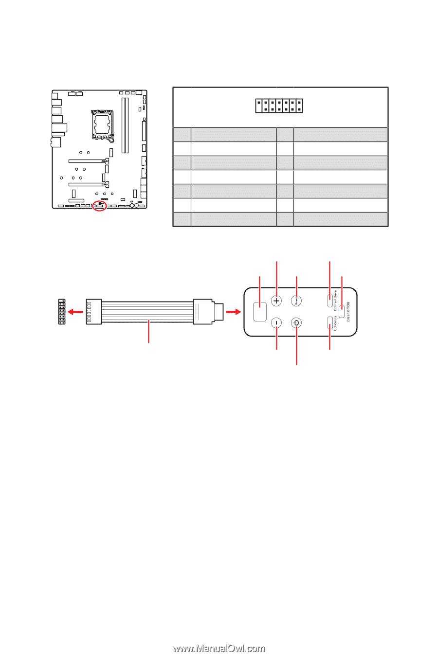
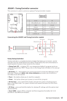
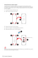
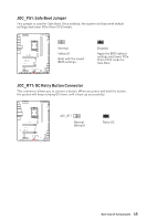
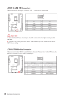
JDASH1 : Tuning Controller connector This connector is used to connect an optional Tuning Controller module. 2 14 1 13 1 No Pin 2 3 MCU_SMB_SCL_M 4 5 VCC5 6 7 PSIN#_R 8 9 OC_RETRY# 10 11 BLK+ 12 13 CLRCMOS_EN 14 NC MCU_SMB_SDA_M Ground FP_RST#_R OC_FS BLKNC Connecting the JDASH1 and Tuning Controller module OC button+ OC Fail Save Debug Code LED Reset Clear CMOS 88 1 Tuning Controller JDASH1 Tuning Controller cable OC button- OC Retry Using Tuning Controller Power Tuning controller is a multiple functions module that helps you to monitor, control and overclock the motherboard more easily. Please follow the instructions below to understand the function of each button on the module. ∙∙ Debug Code LED - it displays CPU core temperature (default), progress and error codes during and after POST. Please refer to the Debug Code LED table in this manual for details. ∙∙ OC button- / + - these buttons are used to decrease/ increase the CPU base clock/ CPU ratio. Please go to BIOS > OC > Direct OC Button and select the CPU BCLK or CPU Ratio to be overclocked. ∙∙ Reset - this button allows you to reset the computer. ∙∙ Power - this button allows you to power on and off the computer. ∙∙ OC Fail Save - press and hold the button and start the system simultaneously to boot in Safe Boot mode. The system will boot with default and lower the PCIe (from CPU) mode. ∙∙ OC Retry - press and hold this button for retrying OC settings until the system boot up successfully. ∙∙ Clear CMOS - power off the computer and than long press this button for 5-10 seconds to reset BIOS with defaults. Overview of Components 43
-
 1
1 -
2
-
3
-
4
-
5
-
6
-
7
-
8
-
9
-
10
-
11
-
12
-
13
-
14
-
15
-
16
-
17
-
18
-
19
-
20
-
21
-
22
-
23
-
24
-
25
-
26
-
27
-
28
-
29
-
30
-
31
-
32
-
33
-
34
-
35
-
36
-
37
-
 38
38 -
 39
39 -
 40
40 -
 41
41 -
 42
42 -
 43
43 -
 44
44 -
 45
45 -
 46
46 -
 47
47 -
 48
48 -
49
-
50
-
51
-
52
-
53
-
54
-
55
-
56
-
57
-
58
-
59
-
60
-
61
-
62
-
63
-
64
-
65
-
66
-
67
-
68
-
69
-
70
-
71
-
72
-
73
 |
 |