MSI P35 NEO COMBO-F User Guide - Page 28
Chassis Intrusion Switch Connector: JCI1, CD-In Connector: CD_IN1, Fan Power Connectors: CPUFAN1, - cpu support
 |
UPC - 816909039276
View all MSI P35 NEO COMBO-F manuals
Add to My Manuals
Save this manual to your list of manuals |
Page 28 highlights
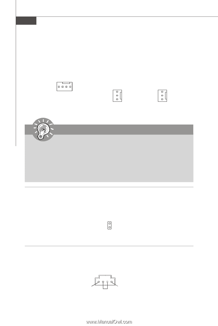
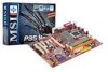
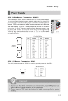
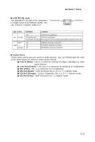
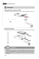
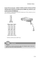
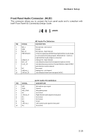
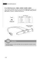
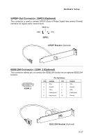
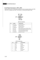
MS-7365 Mainboard Fan Power Connectors: CPUFAN1, SYSFAN1, SYSFAN2 The fan power connectors support system cooling fan with +12V. W hen connecting the wire to the connectors, always note that the red wire is the positive and should be connected to the +12V; the black wire is Ground and should be connected to GND. If the mainboard has a System Hardware Monitor chipset on-board, you must use a specially designed fan with speed sensor to take advantage of the CPU fan control. Control SENSOR +12V GND CPUFAN1 SE NS OR +1 2V GND SYSFAN1 SE NS OR +1 2V GND SYSFAN2 Important 1. Please refer to the recommended CPU fans at processor's official website or consult the vendors for proper CPU cooling fan. 2. Fan cooler set with 3 or 4 pins power connector are both available for CPUFAN1. 3. CPUFAN1 supports fan control. You can setup it in H/W Monitor of BIOS Setup. You can install Dual Core Center utility that will automatically control the CPU fan speed according to the actual CPU temperature. Chassis Intrusion Switch Connector: JCI1 This connector connects to a 2-pin chassis switch. If the chassis is opened, the switch will be short. The system will record this status and show a warning message on the screen. To clear the warning, you must enter the BIOS utility and clear the record. GND 2 CINTRU 1 JCI1 CD-In Connector: CD_IN1 This connector is provided for external audio input. CD_IN1 2-14 R L GND
-
 1
1 -
2
-
3
-
4
-
5
-
6
-
7
-
8
-
9
-
10
-
11
-
12
-
13
-
14
-
15
-
16
-
17
-
18
-
19
-
20
-
21
-
22
-
 23
23 -
 24
24 -
 25
25 -
 26
26 -
 27
27 -
 28
28 -
 29
29 -
 30
30 -
 31
31 -
 32
32 -
 33
33 -
34
-
35
-
36
-
37
-
38
-
39
-
40
-
41
-
42
-
43
-
44
-
45
-
46
-
47
-
48
-
49
-
50
-
51
-
52
-
53
-
54
-
55
-
56
-
57
-
58
-
59
-
60
-
61
-
62
-
63
-
64
-
65
-
66
-
67
-
68
-
69
-
70
-
71
-
72
-
73
-
74
-
75
-
76
-
77
-
78
-
79
-
80
-
81
-
82
-
83
-
84
-
85
-
86
-
87
-
88
-
89
-
90
-
91
 |
 |