MSI PM8PM-V User Guide - Page 15
Fan Power Connectors: CPU_FAN1/ SYS_FAN1, Front Panel Connectors: JFP1, Front Panel Audio Connector - cpu support
 |
UPC - 816909035261
View all MSI PM8PM-V manuals
Add to My Manuals
Save this manual to your list of manuals |
Page 15 highlights
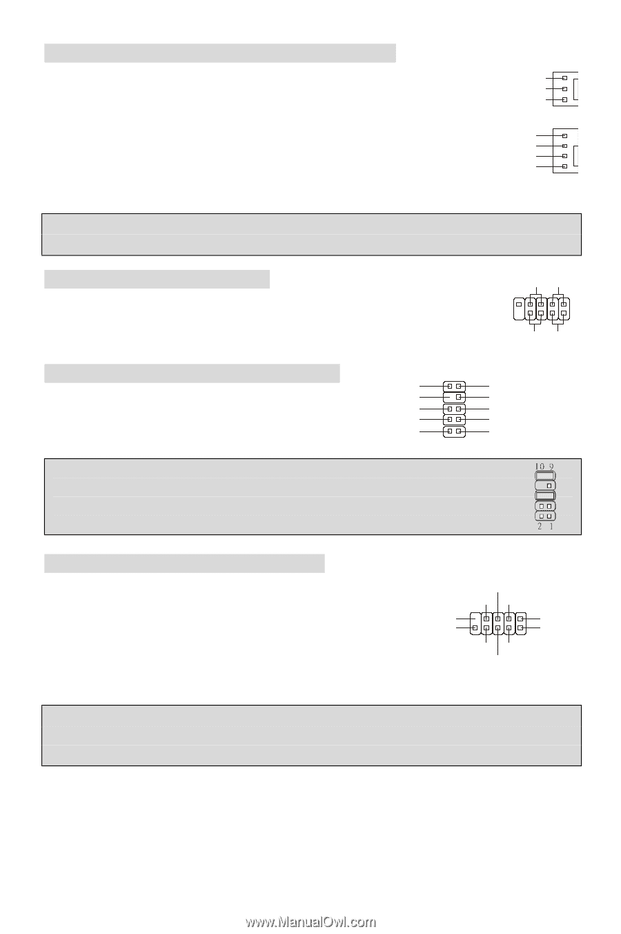
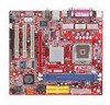
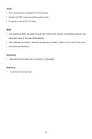
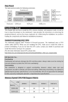
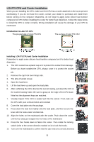
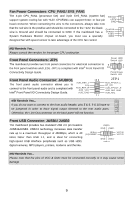
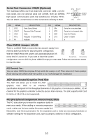
Fan Power Connectors: CPU_FAN1/ SYS_FAN1 The 4-pin CPU_FAN1 (processor fan) and 3-pin SYS_FAN1 (system fan) support system cooling fan with +12V. CPUFAN1 can support three- or four-pin head connector. When connecting the wire to the connectors, always take note Sensor +12V GND that the red wire is the positive and should be connected to the +12V, the black wire is Ground and should be connected to GND. If the mainboard has a System Hardware Monitor chipset on-board, you must use a specially Control Sensor +12V GND designed fan with speed sensor to take advantage of the CPU fan control. MSI Reminds You... Always consult the vendors for the proper CPU cooling fan. Front Panel Connectors: JFP1 Reset HDD Switch LED The mainboard provides two front panel connectors for electrical connection to 9 1 the front panel switches and LEDs. JFP1 is compliant with Intel® Front Panel I/O 10 2 Connectivity Design Guide. PowerPower Switch LED Front Panel Audio Connector: JAUDIO1 10 9 JFP1 AUD_RET_L The front panel audio connector allows you to Key AUD_FPOUT_L HP_ON connect to the front panel audio and is compliant with AUD_RET_R Intel® Front Panel I/O Connectivity Design Guide. AUD_VCC AUD_GND AUD_FPOUT_R AUD_MIC_BIAS AUD_MIC 21 MSI Reminds You... If you do not want to connect to the front audio header, pins 5 & 6, 9 & 10 have to be jumpered in order to have signal output directed to the rear audio ports. Otherwise, the Line-Out connector on the back panel will not function. Front USB Connector: JUSB1/ JUSB2 The mainboard provides two standard USB 2.0 pin headers JUSB1&JUSB2. USB2.0 technology increases data transfer rate up to a maximum throughput of 480Mbps, which is 40 times faster than USB 1.1, and is ideal for connecting high-speed USB interface peripherals such as USB HDD, digital cameras, MP3 players, printers, modems and the like. (9)Key (10)USB0C USB0+ GND USB0- VCC(1) VCC(2) GND USB1USB1+ MSI Reminds You... Please note that the pins of VCC & GND must be connected correctly or it may cause some damage 9
-
 1
1 -
2
-
3
-
4
-
5
-
6
-
7
-
8
-
9
-
 10
10 -
 11
11 -
 12
12 -
 13
13 -
 14
14 -
 15
15 -
 16
16 -
 17
17 -
 18
18 -
 19
19 -
 20
20 -
21
-
22
-
23
-
24
-
25
-
26
-
27
-
28
-
29
-
30
-
31
-
32
-
33
-
34
-
35
-
36
-
37
-
38
-
39
-
40
-
41
-
42
-
43
-
44
-
45
-
46
-
47
-
48
-
49
-
50
-
51
-
52
-
53
-
54
-
55
-
56
-
57
-
58
-
59
-
60
-
61
-
62
-
63
-
64
-
65
-
66
-
67
-
68
-
69
-
70
-
71
-
72
-
73
-
74
-
75
-
76
-
77
-
78
-
79
-
80
-
81
-
82
-
83
-
84
-
85
-
86
-
87
-
88
-
89
-
90
-
91
-
92
-
93
-
94
-
95
-
96
-
97
-
98
-
99
-
100
 |
 |