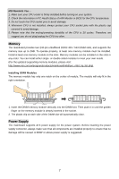
MSI PM8PM-V User Guide - Page 16
Serial Port Connector: COM2 Optional, Clear CMOS Jumper: JCLR1, AGP Accelerated Graphics Port Slot, - ram
 |
UPC - 816909035261
View all MSI PM8PM-V manuals
Add to My Manuals
Save this manual to your list of manuals |
Page 16 highlights
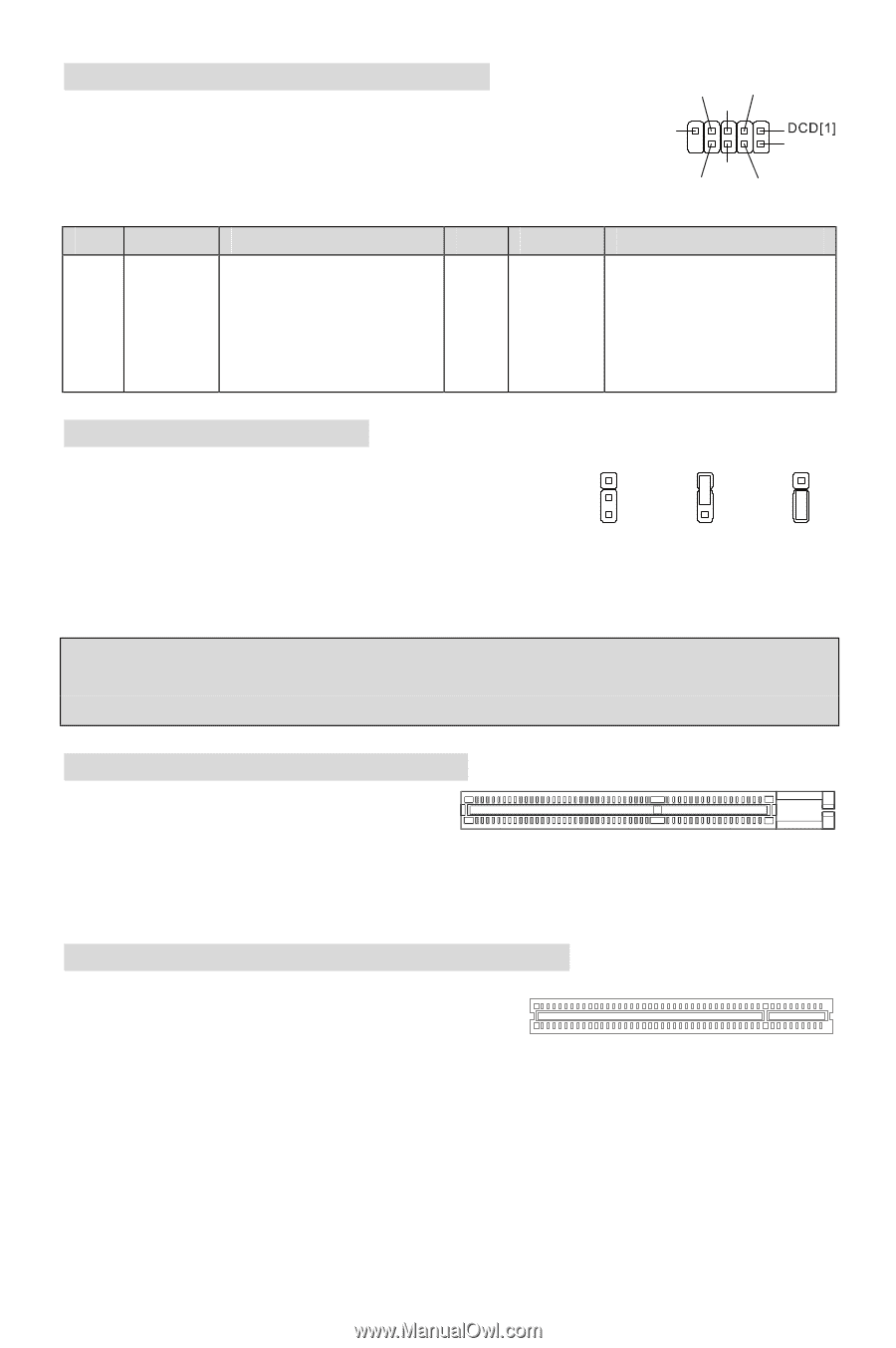
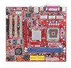
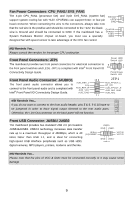
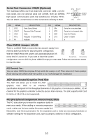
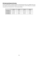
Serial Port Connector: COM2 (Optional) The mainboard offers one 9-pin male DIN connector COM 1 (on the rear panel), and one optional serial port JCOM1. Both are 16550A high speed communication ports that send/receive 16 bytes FIFOs. You can attach a serial mouse or other serial device directly to them. RTS SOUT GND [9]RI SIN[2] DSR CTS DTR PIN SIGNAL DESCRIPTION 1 DCD Data Carry Detect 3 SOUT Receive Data Transmit 5 GND Data 7 RTS Request To Send Ring 9 RI Indicate PIN SIGNAL DESCRIPTION 2 SIN Serial in or receive data 4 DTR Serial out or transmit data 6 DSR Data Set Ready 8 CTS Clear To Send 10 X X Clear CMOS Jumper: JCLR1 There is a CMOS RAM on board that has a power supply from external battery to keep the data of system configuration. 1 2 1 2 1 2 With the CMOS RAM, the system can automatically boot OS 3 3 3 every time it is turned on. If you want to clear the system Keep Data Clear Data configuration, use the JCLR1 (Clear CMOS Jumper) to clear data. Follow the instructions below to clear the data: MSI Reminds You... You can clear CMOS by shorting 2-3 pin while the system is off. Then return to 1-2 pin position. Avoid clearing the CMOS while the system is on; it will damage the mainboard. AGP (Accelerated Graphics Port) Slot The AGP slot allows you to insert the AGP graphics card. AGP is an interface specification designed for the throughput demands of 3D graphics. It introduces a 66MHz, 32-bit channel for the graphics controller to directly access main memory. The slot supports AGP card for 8x/4x at 1.5v (3.3v is not supported). PCI (Peripheral Component Interconnect) Slots The PCI slots allow you to insert the expansion cards to meet your needs. When adding or removing expansion cards, make sure that you unplug the power supply first. Meanwhile, read the documentation for the expansion card to make any necessary hardware or software settings for the expansion card, such as jumpers, switches or BIOS configuration. 10
-
 1
1 -
2
-
3
-
4
-
5
-
6
-
7
-
8
-
9
-
10
-
 11
11 -
 12
12 -
 13
13 -
 14
14 -
 15
15 -
 16
16 -
 17
17 -
 18
18 -
 19
19 -
 20
20 -
 21
21 -
22
-
23
-
24
-
25
-
26
-
27
-
28
-
29
-
30
-
31
-
32
-
33
-
34
-
35
-
36
-
37
-
38
-
39
-
40
-
41
-
42
-
43
-
44
-
45
-
46
-
47
-
48
-
49
-
50
-
51
-
52
-
53
-
54
-
55
-
56
-
57
-
58
-
59
-
60
-
61
-
62
-
63
-
64
-
65
-
66
-
67
-
68
-
69
-
70
-
71
-
72
-
73
-
74
-
75
-
76
-
77
-
78
-
79
-
80
-
81
-
82
-
83
-
84
-
85
-
86
-
87
-
88
-
89
-
90
-
91
-
92
-
93
-
94
-
95
-
96
-
97
-
98
-
99
-
100
 |
 |