MSI X570-A PRO User Manual
MSI X570-A PRO Manual
 |
View all MSI X570-A PRO manuals
Add to My Manuals
Save this manual to your list of manuals |
MSI X570-A PRO manual content summary:
- MSI X570-A PRO | User Manual - Page 1
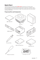
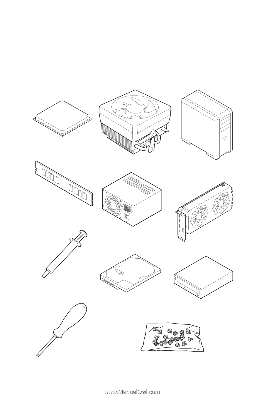
Quick Start Thank you for purchasing the MSI® X570-A PRO motherboard. This Quick Start section provides demonstration to the URL by scanning the QR code. Preparing Tools and Components AMD® AM4 CPU CPU Fan DDR4 Memory Power Supply Unit Chassis Graphics Card Thermal Paste SATA Hard Disk Drive - MSI X570-A PRO | User Manual - Page 2
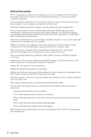
adhere to the following instructions to ensure successful motherboard checked by service personnel: ƒ Liquid has penetrated into the computer. ƒ The motherboard has been exposed to moisture. ƒ The motherboard does not work well or you can not get it work according to user guide. ƒ The motherboard - MSI X570-A PRO | User Manual - Page 3
Installing a Processor https://youtu.be/Xv89nhFk1vc 3 2 1 5 4 8 6 9 7 Quick Start 3 - MSI X570-A PRO | User Manual - Page 4
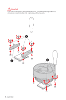
Important If you are installing the screw-type CPU heatsink, please follow the figure below to remove the retention module first and then install the heatsink. 1 2 3 4 Quick Start - MSI X570-A PRO | User Manual - Page 5
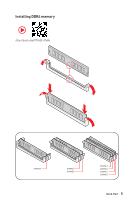
Installing DDR4 memory http://youtu.be/T03aDrJPyQs DIMMA2 DIMMA2 DIMMB2 DIMMA1 DIMMA2 DIMMB1 DIMMB2 Quick Start 5 - MSI X570-A PRO | User Manual - Page 6
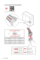
Connecting the Front Panel Header http://youtu.be/DPELIdVNZUI POPWOEWRELREHLDD-EDDL+ED RESET SW POWER SW Power LED Power Switch - -+ -- ++ JFP1 2 1 + 10 9 Reserved HDD LED Reset Switch 1 HDD LED + 2 3 HDD LED - 4 5 Reset Switch 6 7 Reset Switch 8 9 Reserved 10 Power LED + - MSI X570-A PRO | User Manual - Page 7
Installing the Motherboard 1 2 3 Quick Start 7 BAT1 - MSI X570-A PRO | User Manual - Page 8
Connecting the Power Connectors http://youtu.be/gkDYyR_83I4 ATX_PWR1 CPU_PWR1 8 Quick Start CPU_PWR2 - MSI X570-A PRO | User Manual - Page 9
Installing SATA Drives http://youtu.be/RZsMpqxythc 2 1 3 5 4 Quick Start 9 - MSI X570-A PRO | User Manual - Page 10
Installing a Graphics Card http://youtu.be/mG0GZpr9w_A 1 3 2 5 10 Quick Start 4 6 - MSI X570-A PRO | User Manual - Page 11
Connecting Peripheral Devices Processor with integrated graphics Quick Start 11 - MSI X570-A PRO | User Manual - Page 12
Power On 1 2 3 4 12 Quick Start - MSI X570-A PRO | User Manual - Page 13
Audio Console 23 Overview of Components 25 CPU Socket ...27 DIMM Slots...28 PCI_E1~5: PCIe Expansion Slots 29 M2_1~2: M.2 Slots (Key M 30 SATA1~6: SATA 6Gb/s Connectors 31 JFP1, JFP2: Front Panel Connectors 31 CPU_PWR1~2, ATX_PWR1: Power Connectors 32 CPU_FAN1, PUMP_FAN1, SYS_FAN1~4: Fan - MSI X570-A PRO | User Manual - Page 14
38 JRAINBOW1~2: Addressable RGB LED connectors 39 Installing OS, Drivers & Utilities 40 Installing Windows® 10 40 Installing Drivers 40 Installing Utilities 40 BIOS Setup ...41 Entering BIOS Setup 41 Resetting BIOS...42 Updating BIOS...42 EZ Mode ...44 Advanced Mode ...46 SETTINGS...47 - MSI X570-A PRO | User Manual - Page 15
y Dual channel memory architecture y Supports non-ECC UDIMM memory y Supports ECC UDIMM memory (non-ECC mode) y Supports un-buffered memory * Please refer www.msi.com for more information on compatible memory. y 1x PCIe 4.0/ 3.0 x16 slot (PCI_E1) ƒ 3rd Gen AMD Ryzen™ support PCIe 4.0 x16 mode ƒ 2nd - MSI X570-A PRO | User Manual - Page 16
page y 6x SATA 6Gb/s ports ƒ SATA3~SATA6 ports (from AMD® X570 Chipset) ƒ SATA1~SATA2 ports (from ASMedia ASM1061) y 2x M.2 slots (Key M)* ƒ M2_1 slot (from AMD® Processor) ˜ Supports PCIe 4.0 x4 (3rd Gen AMD Ryzen™) ˜ Supports PCIe 3.0 x4 (2nd Gen AMD Ryzen™/ Ryzen™ with Radeon™ Vega Graphics - MSI X570-A PRO | User Manual - Page 17
y 1x Front panel audio connector y 2x System panel connectors y 1x TPM module connector y 1x Serial port connector y 1x Clear CMOS jumper y 1x Chassis Intrusion connector y 2x 4-pin RGB LED connectors y 2x 3-pin RAINBOW LED connectors y 4x EZ Debug LEDs Back Panel Connectors y 1x Flash BIOS Button - MSI X570-A PRO | User Manual - Page 18
ATX Form Factor y 12 in. x 9.6 in. (30.4 cm x 24.3 cm) y 1x 256 Mb flash y UEFI AMI BIOS y ACPI 6.2, SM BIOS 3.2 y Multi-language y Drivers y DRAGON CENTER y CPU-Z MSI GAMING y MSI App Player (BlueStacks) y Google Chrome™ ,Google Toolbar, Google Drive y Norton™ Internet Security Solution y DRAGON - MSI X570-A PRO | User Manual - Page 19
(RGB) ƒ Mystic Light Extension (RAINBOW) ƒ Mystic Light Sync ƒ EZ DEBUG LED y Protection ƒ PCIe Steel Armor y Performance ƒ Multi GPU-CrossFire Technology ƒ DDR4 Boost ƒ Core Boost ƒ GAME Boost ƒ USB with type A+C ƒ AMD Turbo USB 3.2 Gen 2 y BIOS ƒ Click BIOS 5 ƒ Flash BIOS Specifications 19 - MSI X570-A PRO | User Manual - Page 20
check the contents of your motherboard package. It should contain: Motherboard X570-A PRO Cable SATA 6Gb/s Cables 2 8.5H M.2 screws 2 Accessories Case Badge 1 Product Registration Card 1 Application DVD Driver DVD 1 Documentation Quick Installation Guide 1 Important If any of the - MSI X570-A PRO | User Manual - Page 21
Block Diagram 2 Channel DDR4 Memory Processor 1x M.2 PCI Express Bus 1x M.2 6x SATA 6Gb/s 6x USB 2.0 PCIE PCH 2x USB 3.2 Gen1 2x USB 3.2 Gen2 Realtek Front Audio Jacks ALC1220 Rear Audio Jacks NUVOTON 6797 6x USB 3.2 Gen1 1x Realtek 8111H LAN Block Diagram 21 - MSI X570-A PRO | User Manual - Page 22
Rear I/O Panel PS/2 Flash BIOS Button USB 3.2 Gen1 Type-A LAN USB 3.2 Gen 2 Type-A* Audio Ports Flash BIOS Port USB 2.0 Type-A USB 3.2 Gen 1 Type-A USB 3.2 Gen 2 Type-C* ●●● Line-In/ Side Speaker Out ● Line-Out/ Front Speaker Out Mic In (●: connected, Blank: empty) 22 Rear - MSI X570-A PRO | User Manual - Page 23
or balance the right/left side of the speakers that you plugged in front or rear panel by adjust the bar. y Jack Status - depicts all render and capture devices currently connected with your computer. y Connector Settings - configures the connection settings. Auto popup dialog When you plug into - MSI X570-A PRO | User Manual - Page 24
Audio jacks to headphone and microphone diagram Audio jacks to stereo speakers diagram AUDIO INPUT Audio jacks to 7.1-channel speakers diagram AUDIO INPUT Rear Front Side Center/ Subwoofer 24 Rear I/O Panel - MSI X570-A PRO | User Manual - Page 25
Overview of Components CPU_PWR2 CPU_PWR1 Processor Socket CPU_FAN1 JRGB2 JRAINBOW2 PUMP_FAN1 DIMMB2 DIMMB1 DIMMA2 DIMMA1 PCI_E1 JBAT1 PCI_E2 PCI_E3 PCI_E4 JCI1 PCI_E5 JAUD1 BAT1 JRGB1 JTPM1 SYS_FAN1 SYS_FAN2 SYS_FAN3 JUSB3 JUSB2 JUSB1 JCOM1 SYS_FAN4 ATX_PWR1 M2_1 SATA▼5▲6 SATA▼3▲4 SATA - MSI X570-A PRO | User Manual - Page 26
Audio Connector Clear CMOS (Reset BIOS) Jumper Chassis Intrusion Connector JCOM1 Serial Port Connector JFP1, JFP2 JRAINBOW1~2 JRGB1~2 Front Panel Connectors Addressable RGB LED connectors RGB LED connectors JUSB1~2 USB 2.0 Connectors JUSB3~4 USB 3.2 Gen1 Connectors M2_1~2 M.2 Slots (Key - MSI X570-A PRO | User Manual - Page 27
has a yellow triangle to assist in correctly lining up the CPU for motherboard placement. The yellow triangle is the Pin 1 indicator. Important y When changing the processor, the system configuration could be cleared and reset BIOS to default values, due to the AM4 processor's architecture. y Always - MSI X570-A PRO | User Manual - Page 28
in the DIMMA2 slot first. y motherboard. y Some memory may operate at a lower frequency than the marked value when overclocking due to the memory frequency operates dependent on its Serial Presence Detect (SPD). Go to BIOS compatibility of installed memory module depend on installed CPU and - MSI X570-A PRO | User Manual - Page 29
use a tool such as MSI Gaming Series Graphics Card Bolster to support its weight to prevent deformation of the slot. y For a single PCIe for any necessary additional hardware or software changes. PCIe bandwidth table Slot Single 2-Way PCI_E1 (CPU) @4.0 x16* or @3.0 x16** or @3.0 x8*** @4.0 x16 - MSI X570-A PRO | User Manual - Page 30
Slots (Key M) M2_1 M2_2 The following table describes the relationship between the M.2 slots and the PCIe bandwidth of the processors. Slots 3rd Gen AMD Ryzen™ M2_1 (CPU the M.2 slot at a 30-degree angle. 3. Secure the M.2 SSD in place with the 8.5H M.2 screw provided with motherboard package. - MSI X570-A PRO | User Manual - Page 31
that the flat connector be connected to the motherboard for space saving purposes. JFP1, JFP2: Front Panel Connectors These connectors connect to the switches and LEDs on the front panel. Power LED Power Switch - -+ -- ++ JFP1 2 1 + 10 9 Reserved HDD LED Reset Switch 1 HDD LED - MSI X570-A PRO | User Manual - Page 32
CPU_PWR1~2, ATX_PWR1: Power Connectors These connectors allow you to connect an ATX power supply. 1 2 3 4 1 2 1 2 3 12 24 4 5 6 ATX_PWR1 7 8 1 13 9 10 11 12 8 4 Ground Ground Ground proper ATX power supply to ensure stable operation of the motherboard. 32 Overview of Components - MSI X570-A PRO | User Manual - Page 33
fan speed in BIOS > HARDWARE MONITOR. Select PWM mode or DC mode There are gradient points of the fan speed that allow you to adjust fan speed in relation to CPU temperature. Important Make sure fans are working properly after switching the PWM/ DC mode. Pin definition of fan connectors PWM Mode - MSI X570-A PRO | User Manual - Page 34
Power and Ground pins must be connected correctly to avoid possible damage. JUSB1~2: USB 2.0 Connectors These connectors allow you to connect USB 2.0 ports on the front panel. 2 10 1 9 1 VCC 2 3 USB0- 4 5 USB0+ 6 7 Ground 8 9 No Pin 10 VCC USB1USB1+ Ground NC Important y Note - MSI X570-A PRO | User Manual - Page 35
allows you to connect audio jacks on the front panel. 2 10 1 9 1 MIC L 2 Ground 3 MIC R 4 NC 5 Head Phone R 6 MIC Detection 7 SENSE_SEND 8 No Pin 9 Head Phone L 10 Head Phone Detection JCOM1: Serial Port Connector This connector allows you to connect the optional serial port - MSI X570-A PRO | User Manual - Page 36
displayed on screen when the computer is turned on. Resetting the chassis intrusion warning 1. Go to BIOS > SETTINGS > Security > Chassis Intrusion Configuration. 2. Set Chassis Intrusion to Reset. 3. Press F10 to save and exit and then press the Enter key to select Yes. 36 Overview of Components - MSI X570-A PRO | User Manual - Page 37
motherboard to save system configuration data. If you want to clear the system configuration, set the jumper to clear the CMOS memory. Keep Data (default) Clear CMOS/ Reset BIOS Resetting BIOS LEDs indicate the debug status of the motherboard. CPU - indicates CPU is not detected or fail. DRAM - - MSI X570-A PRO | User Manual - Page 38
y An JRGB connector supports up to 2 meters continuous 5050 RGB LED strips (12V/G/R/B) with the maximum power rating of 3A (12V). y Always turn off the power supply and unplug the power cord from the power outlet before installing or removing the RGB LED strip. y Please use MSI's software to - MSI X570-A PRO | User Manual - Page 39
connector and the JRAINBOW connector provide different voltages, and connecting the 5V LED strip to the JRGB connector will result in damage to the LED strip. Important y The JRAINBOW connector supports (5V). In the case of 20% brightness, the connector supports up to 200 LEDs. y Always turn off the - MSI X570-A PRO | User Manual - Page 40
Run DVDSetup.exe to open the installer. If you turn off the AutoPlay feature from the Windows Control Panel, you can still manually execute the DVDSetup.exe from the root path of the MSI Driver Disc. 4. The installer will find and list all necessary drivers in the Drivers/Software tab. 5. Click the - MSI X570-A PRO | User Manual - Page 41
also refer to the HELP information panel for BIOS item description. y The pictures in this chapter are for reference only and may vary from the product you purchased. y The BIOS items will vary with the processor. Entering BIOS Setup Press Delete key, when the Press DEL key to enter Setup Menu, F11 - MSI X570-A PRO | User Manual - Page 42
refer to the Clear CMOS jumper section for resetting BIOS. Updating BIOS Updating BIOS with M-FLASH Before updating: Please download the latest BIOS file that matches your motherboard model from MSI website. And then save the BIOS file into the USB flash drive. Updating BIOS: 1. Insert the USB - MSI X570-A PRO | User Manual - Page 43
download the latest BIOS file that matches your motherboard model from MSI® website and rename the BIOS file to MSI.ROM. And then, save the MSI.ROM file to the root of USB flash drive. Important Only the FAT32 format USB flash drive supports updating BIOS by Flash BIOS Button. 1. Connect power - MSI X570-A PRO | User Manual - Page 44
search page, only the F6, F10 and F12 function keys are available. y Language - allows you to select language of BIOS setup. y System information - shows the CPU/ DDR speed, CPU/ MB temperature, MB/ CPU type, memory size, CPU/ DDR voltage, BIOS version and build date. y Boot device priority bar - MSI X570-A PRO | User Manual - Page 45
and RGB Light Control by clicking on their respective button. y M-Flash - click on this button to display the M-Flash menu that provides the way to update BIOS with a USB flash drive. y Hardware Monitor - click on this button to display the Hardware Monitor menu that allows you to manually control - MSI X570-A PRO | User Manual - Page 46
BIOS with a USB flash drive. ƒ OC PROFILE - allows you to manage overclocking profiles. ƒ HARDWARE MONITOR - allows you to set the speeds of fans and monitor voltages of system. ƒ BOARD EXPLORER - provides the information of installed devices on this motherboard. y Menu display - provides BIOS - MSI X570-A PRO | User Manual - Page 47
1 to 31 can be keyed by numeric function keys. The year can be adjusted by users. f System Time Sets the system time. Use tab key to switch between time elements. of the device and motherboard. f System Information Shows detailed system information, including CPU type, BIOS version, and Memory - MSI X570-A PRO | User Manual - Page 48
protocol of PCIe x16 slots for matching different installed devices. [Auto] This item will be configured automatically by BIOS. [Gen1] Enables PCIe Gen1 support only. [Gen2] Enables PCIe Gen2 support only. [Gen3] Enables PCIe Gen3 support only. [Gen4] Enables PCIe Gen4 support only. fPCIe SlotX - MSI X570-A PRO | User Manual - Page 49
disable the SATA hot plug support. [Enabled] Enables hot plug support for the SATA ports. [Disabled] Disables hot plug support for the SATA ports. fHD Device. fIntegrated Graphics [Auto] (optional) If set to Force, BIOS will enable the integrated graphics controller. fUMA Frame Buffer Size [Auto] - MSI X570-A PRO | User Manual - Page 50
serial port x (COM). If set to Auto, BIOS will optimize the IRQ automatically or you can set it manually. f Power Management Setup Sets system Power Management of ErP Optimize the system power consumption according to ErP regulation. It will not support S4 & S5 wake up by USB, PCI and PCIe devices. - MSI X570-A PRO | User Manual - Page 51
CSM] Select CSM (Compatibility Support Module) or UEFI to enter the sub-menu. This sub-menu will appear when BIOS UEFI/CSM Mode sets to UEFI. f Wake Up Event Setup date/hour/minute/second in these fields (using the + and - keys to select the date & time settings). fResume By PCI-E Device [Disabled - MSI X570-A PRO | User Manual - Page 52
hot key on PS/2 keyboard is detected. [Disabled] Disables this function. fHot Key [Ctrl+Space] Selects a combination of keys as a hot key to S3/S4/S5 by PS/2 Keyboard to Hot Key. f Secure Erase+ Enables or disables Secure Erase or disables the CMOS data to be resumed automatically when the system cannot boot - MSI X570-A PRO | User Manual - Page 53
BIOS when BIOS UEFI/CSM Mode sets to UEFI. [UEFI] [LEGACY+UEFI] Enables UEFI BIOS boot mode support only. Enables both Legacy BIOS boot mode and UEFI BIOS any previous set password from CMOS memory. You will be prompted to confirm the password. You may also press Esc key to abort the selection. To - MSI X570-A PRO | User Manual - Page 54
key for accessing the system. fAMD fTPM switch [AMD CPU fTPM] Selects TPM device. This item will appear when Security Device Support is enabled. [AMD CPU fTPM] Select it for AMD Firmware TPM. [AMD CPU a warning message. [Reset] Clear the warning and Exit Exit BIOS setup without saving any - MSI X570-A PRO | User Manual - Page 55
If it occurs, please clear the CMOS data and restore the default settings. f A-XMP [Disabled] Please enable A-XMP or select a profile of memory module for overclocking the memory. This item will be available when the installed processor, memory modules and motherboard support this function. f DRAM - MSI X570-A PRO | User Manual - Page 56
allows you to set the voltages related to CPU. If set to Auto, BIOS will set these voltages automatically or you can set it manually. f DRAM Voltages control [Auto] These options allows you to set the voltages related to memory. If set to Auto, BIOS will set these voltages automatically or you can - MSI X570-A PRO | User Manual - Page 57
BIOS settings. f CPU Specifications Press Enter to enter the sub-menu. This sub-menu displays the information of installed CPU. You can also access this information menu at any time by pressing [F4]. Read only. fCPU Technology Support Press Enter to enter the sub-menu. The sub-menu shows the key - MSI X570-A PRO | User Manual - Page 58
Cool'n'Quiet technology can effectively and dynamically lower CPU speed and power consumption. fSVM Mode [Enabled] Enables/ disables the AMD SVM (Secure Virtual Machine) Mode. fBIOS PSP Support [Enabled] (optional) Enables/ disables the BIOS PSP support. It manages PSP sub-items including all C2P - MSI X570-A PRO | User Manual - Page 59
provides the way to update BIOS with a USB flash drive. Please download the latest BIOS file that matches your motherboard model from MSI website, save the BIOS file into your USB flash drive. And then follow the steps below to update BIOS. 1. Insert the USB flash drive that contains the update - MSI X570-A PRO | User Manual - Page 60
Load from ROM Load OC profile from BIOS ROM. f OC Profile Save to USB Save OC profile to the USB flash drive. The USB flash drive should be FAT/ FAT32 format only. f OC Profile Load from USB Load OC profile from the USB flash drive. The USB flash drive should be FAT/ FAT32 format only - MSI X570-A PRO | User Manual - Page 61
MONITOR Temperature & Speed Fan Manage Setting Buttons Temperature/ Voltage display f Temperature & Speed Shows the current CPU temperature, system temperature and fans' Temperature/ Voltage display Shows CPU/ system temperature and the current voltages of CPU, system and memory. BIOS Setup 61 - MSI X570-A PRO | User Manual - Page 62
module supports XMP How to enable A-XMP Power on and press Delete key to enter BIOS Setup menu. Here are two methods below to enable A-XMP. Method 1. BIOS EZ button Click A-XMP button 1 or 2 to enable XMP profile 1 or profile 2. Profile 2 Toggle Profile1 Toggle A-XMP Indicator Method 2. BIOS item - MSI X570-A PRO | User Manual - Page 63
AMD RAID Configuration The following are the RAID levels supported by RAIDXpert2. RAID 0 (Striping) breaks the data menu 1. Power on and press Delete key to enter BIOS Setup menu. 2. Press F7 to switch to Advanced mode from EZ mode. 3. Go to BIOS > SETTINGS > Advanced > Integrated Peripherals - MSI X570-A PRO | User Manual - Page 64
As previously mentioned, enable RAIDXpert2 Configuration Utility. 2. Go to BIOS > SETTINGS > Advanced > RAIDXpert2 Configuration Utility > Physical Disk Physical Disk setting to Enabled. 4. Select OK, then press Enter. 5. Review the warning message, if you want to proceed, select YES, then press - MSI X570-A PRO | User Manual - Page 65
from the first array in the Arrays section. To create an array 1. As previously mentioned, enable RAIDXpert2 Configuration Utility. 2. Go to BIOS > SETTINGS > Advanced > RAIDXpert2 Configuration Utility > Array Management > Create Array sub-menu. 3. Select the RAID level from the Select RAID Level - MSI X570-A PRO | User Manual - Page 66
As previously mentioned, enable RAIDXpert2 Configuration Utility. 2. Go to BIOS > SETTINGS > Advanced > RAIDXpert2 Configuration Utility > Array change the setting to Enabled. 4. Enter Delete Array(s) sub-menu. 5. Review the warning message, if you want to proceed, Select Confirm and change the - MSI X570-A PRO | User Manual - Page 67
button to install a third party RAID driver. 2. When prompted, insert the USB flash drive with AMD RAID Drivers and then click Browse. ƒ To make an AMD RAID Drivers USB flash drive. Insert the MSI Control Panel, you can still manually execute the DVDSetup.exe from the root path of the MSI Driver - MSI X570-A PRO | User Manual - Page 68
USB device is listed in Windows® Device Manager. y Connect the USB device to other USB port on the motherboard rear IO panel. The computer does not boot after updating the BIOS y Clear the CMOS. y Use the secondary BIOS to bootup the system (Only for motherboard with Dual BIOS) 68 Troubleshooting - MSI X570-A PRO | User Manual - Page 69
and used in accordance with the instructions, may cause harmful interference to of the following EU Directives as may be applicable: RED 2014/53/EU; Low Voltage Directive 2014/35/EU; for regulatory matters is MSI, MSI-NL Eindhoven 5706 5692 ER California, USA: The button cell battery may contain - MSI X570-A PRO | User Manual - Page 70
sein de la communauté européenne. Par conséquent vous pouvez retourner localement ces matériels dans les points de collecte. MSI WEEE 2002/96/EC 13 2005 MSI MSI EC ESPAÑOL MSI como empresa comprometida con la protección del medio ambiente, recomienda: Bajo la directiva 2002/96/EC de la Uni - MSI X570-A PRO | User Manual - Page 71
Tyto výrobky můžete odevzdat v místních sběrnách. MAGYAR Annak érdekében, hogy környezetünket megvédjük, illetve környezetvédőként fellépve az MSI emlékezteti Önt, hogy ... Az Európai Unió („EU") 2005. augusztus 13-án hatályba lépő, az elektromos és elektronikus berendezések hulladékairól szóló 2002 - MSI X570-A PRO | User Manual - Page 72
The MSI logo Support If a problem arises with your system and no solution can be obtained from the user guide, please contact your place of purchase or local distributor. Alternatively, please try the following help resources for further guidance. y Visit the MSI website for technical guide, BIOS
-
 1
1 -
 2
2 -
 3
3 -
 4
4 -
 5
5 -
 6
6 -
 7
7 -
8
-
9
-
10
-
11
-
12
-
13
-
14
-
15
-
16
-
17
-
18
-
19
-
20
-
21
-
22
-
23
-
24
-
25
-
26
-
27
-
28
-
29
-
30
-
31
-
32
-
33
-
34
-
35
-
36
-
37
-
38
-
39
-
40
-
41
-
42
-
43
-
44
-
45
-
46
-
47
-
48
-
49
-
50
-
51
-
52
-
53
-
54
-
55
-
56
-
57
-
58
-
59
-
60
-
61
-
62
-
63
-
64
-
65
-
66
-
67
-
68
-
69
-
70
-
71
-
72
 |
 |
1
Quick Start
Quick Start
Thank you for purchasing the MSI
®
X570-A PRO
motherboard. This Quick Start
section provides demonstration diagrams about how to install your computer. Some
of the installations also provide video demonstrations. Please link to the URL to watch
it with the web browser on your phone or tablet. You may have even link to the URL by
scanning the QR code.
Preparing Tools and Components
DDR4 Memory
Graphics Card
SATA Hard Disk Drive
SATA DVD Drive
Phillips Screwdriver
Chassis
Power Supply Unit
A Package of Screws
Thermal Paste
CPU Fan
AMD
®
AM4 CPU