MSI Z270-A PRO User Manual - Page 34
JTPM1: TPM Module Connector, JBAT1: Clear CMOS (Reset BIOS) Jumper, Resetting BIOS to default values - manual
 |
View all MSI Z270-A PRO manuals
Add to My Manuals
Save this manual to your list of manuals |
Page 34 highlights
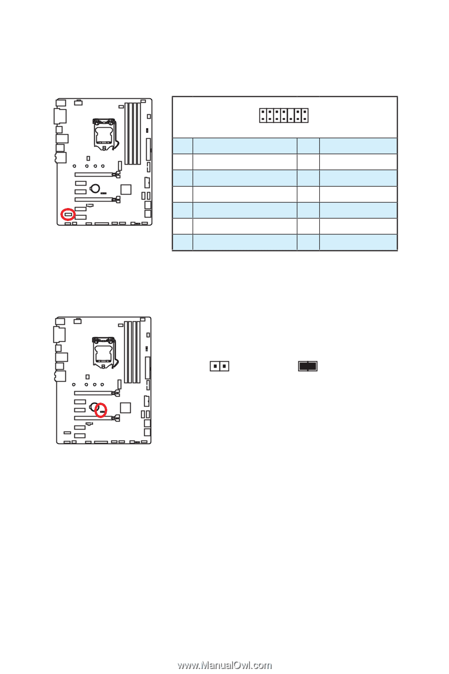
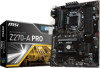
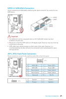
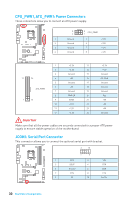
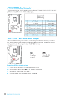
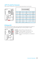
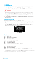
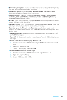
JTPM1: TPM Module Connector This connector is for TPM (Trusted Platform Module). Please refer to the TPM security platform manual for more details and usages. 2 14 1 13 1 LPC Clock 2 3V Standby power 3 LPC Reset 4 5 LPC address & data pin0 6 3.3V Power Serial IRQ 7 LPC address & data pin1 8 9 LPC address & data pin2 10 5V Power No Pin 11 LPC address & data pin3 12 13 LPC Frame 14 Ground Ground JBAT1: Clear CMOS (Reset BIOS) Jumper There is CMOS memory onboard that is external powered from a battery located on the motherboard to save system configuration data. If you want to clear the system configuration, set the jumper to clear the CMOS memory. Keep Data (default) Clear CMOS/ Reset BIOS Resetting BIOS to default values 1. Power off the computer and unplug the power cord 2. Use a jumper cap to short JBAT1 for about 5-10 seconds. 3. Remove the jumper cap from JBAT1. 4. Plug the power cord and power on the computer. 34 Overview of Components
-
 1
1 -
2
-
3
-
4
-
5
-
6
-
7
-
8
-
9
-
10
-
11
-
12
-
13
-
14
-
15
-
16
-
17
-
18
-
19
-
20
-
21
-
22
-
23
-
24
-
25
-
26
-
27
-
28
-
 29
29 -
 30
30 -
 31
31 -
 32
32 -
 33
33 -
 34
34 -
 35
35 -
 36
36 -
 37
37 -
 38
38 -
 39
39 -
40
-
41
-
42
-
43
-
44
-
45
-
46
-
47
-
48
-
49
-
50
-
51
-
52
-
53
-
54
-
55
-
56
-
57
-
58
-
59
-
60
-
61
-
62
-
63
-
64
-
65
-
66
-
67
-
68
-
69
-
70
-
71
-
72
-
73
-
74
-
75
-
76
-
77
-
78
-
79
-
80
-
81
-
82
-
83
-
84
-
85
-
86
-
87
 |
 |