MSI Z68MA User Guide - Page 35
SPDIF, Ground
 |
View all MSI Z68MA manuals
Add to My Manuals
Save this manual to your list of manuals |
Page 35 highlights
Chapter 1 115V MS-7676 USB 2.0 Expansion Connectors: JUSB1/ JUSB2/ JUSB3 This connector is designed for connecting high-speed USB peripherals such as USB HDDs, digital cameras, MP3 players, printers, modems, and many others. 2.V4C.U6CS.U8BS1.1G0B-r.1No+uCnd 1.V3C.U5CS.U7BS.0G9B-.rN0o+ounPdin * The MB layout in this figure is for reference only. USB 2.0 Bracket (optional) Important Note that the VCC and GND pins must be connected correctly to avoid possible damage. S/PDIF-Out Expansion Connector: JSP1 This connector uses the S/PDIF (Sony & Phillips Digital Interconnect Format) interface for digital audio transmission. 3.V2C.S1C.PGDrIoFund * The MB layout in this figure is for reference only. S/PDIF-Out Bracket (optional) 1-25 115V
-
 1
1 -
2
-
3
-
4
-
5
-
6
-
7
-
8
-
9
-
10
-
11
-
12
-
13
-
14
-
15
-
16
-
17
-
18
-
19
-
20
-
21
-
22
-
23
-
24
-
25
-
26
-
27
-
28
-
29
-
 30
30 -
 31
31 -
 32
32 -
 33
33 -
 34
34 -
 35
35 -
 36
36 -
 37
37 -
 38
38 -
 39
39 -
 40
40 -
41
-
42
-
43
-
44
-
45
-
46
-
47
-
48
-
49
-
50
-
51
-
52
-
53
-
54
-
55
-
56
-
57
-
58
-
59
-
60
-
61
-
62
-
63
-
64
-
65
-
66
-
67
-
68
-
69
-
70
-
71
-
72
-
73
-
74
-
75
-
76
-
77
-
78
-
79
-
80
 |
 |

1-25
MS-7676
Chapter 1
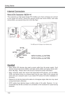
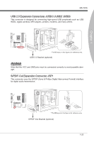
USB 2.0 Expans±on Connectors: JUSB1/ JUSB2/ JUSB3
Th±s connector ±s des±gned for connect±ng h±gh-speed USB per±pherals such as USB
HDDs, d±g±tal cameras, MP3 players, pr±nters, modems, and many others.
10.NC
8.Ground
6.USB1+
4.USB1-
2.VCC
1.VCC
3.USB0-
5.USB0+
7.Ground
9.No Pin
* The MB layout ±n th±s figure ±s for reference only.
USB 2.0 Bracket (opt±onal)
Important
Note that the VCC and GND p±ns must be connected correctly to avo±d poss±ble dam-
age.
S/PDIF-Out Expans±on Connector: JSP1
Th±s connector uses the S/PDIF (Sony & Ph±ll±ps D±g±tal Interconnect Format) ±nterface
for d±g±tal aud±o transm±ss±on.
3.VCC
2.SPDIF
1.Ground
* The MB layout ±n th±s figure ±s for reference only.
S/PDIF-Out Bracket (opt±onal)