Mackie 802-VLZ3 Owner's Manual - Page 6
Hookup Diagrams - rude solo
 |
View all Mackie 802-VLZ3 manuals
Add to My Manuals
Save this manual to your list of manuals |
Page 6 highlights
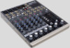
802-VLZ3 Hookup Diagrams Electric Guitar Acoustic Microphone Guitar Bass Guitar Amplifier modeler DI Box MIC 1 MIC 2 MIC 3 MAIN OUT BALANCED L BAL/UNBAL R L Send R 802 BAL OR UNBAL BAL OR UNBAL MONO L LINE IN 1 LINE IN 2 BAL LINE IN 3 OR UNBAL R +4 MIC MAIN OUTPUT LEVEL L L R R TAPE IN TAPE OUT INSERT U M-1IC0GdABIVN INSERT U M-1IC0GdABIVN LINE IN 4 LOW CUT 100 Hz 18dB/OCT MIC GAIN MONO L BAL OR UNBAL R MONO L BAL OR UNBAL R 0 60 +15dB - 45dB GAIN 0 60 +15dB - 45dB GAIN 0 60 GAIN LINE IN 5-6 LINE IN 7-8 MAIN OUT AUX SEND BAL/UNBAL L BAL/UNBAL BAL/UNBAL L3 L R R4 R ST RETURN ALT OUTPUT CR OUTPUT PHANTOM POWER PHONES Effects Processor Return (connected to aux send) Return Vocal Compressor (connected to Insert) Send Return Compressor (connected to Insert) U AUX U AUX U AUX U AUX U AUX OO +15 U EQ HI 12kHz -15 +15 U MID 2.5kHz -15 +15 U LOW 80Hz -15 +15 PAN OO +15 U EQ HI 12kHz -15 +15 U MID 2.5kHz -15 +15 U LOW 80Hz -15 +15 PAN OO +15 U EQ HI 12kHz -15 +15 U MID 2.5kHz -15 +15 U LOW 80Hz -15 +15 PAN OO +15 U EQ HI 12kHz -15 +15 U MID 2.5kHz -15 +15 U LOW 80Hz -15 +15 PAN OO +15 U EQ HI 12kHz -15 +15 U MID 2.5kHz -15 +15 U LOW 80Hz -15 +15 PAN LR 1 MUTE ALT 3-4 PRE FADER SOLO U LR 2 MUTE ALT 3-4 PRE FADER SOLO U LR 3-4 MUTE ALT 3-4 PRE FADER SOLO U LR 5-6 MUTE ALT 3-4 PRE FADER SOLO U LR 7-8 MUTE ALT 3-4 PRE FADER SOLO U PRE POST U AUX MASTER SEND OO +10 POWER CONTROL ROOM SOURCE MAIN MIX ALT 3-4 TAPE ASSIGN TO MAIN MIX U STEREO RETURN +20 OO LEFT RIGHT 0dB=0dBu 20 15 10 6 3 0 2 4 7 LEVEL SET 10 20 30 RUDE SOLO U OO MAX U PHONES OO +12dB LEVEL OO +12dB LEVEL OO +12dB LEVEL OO +12dB LEVEL OO +12dB LEVEL OO +10dB CTL ROOM/SUBMIX OO +12dB MAIN MIX SA1530z Powered Speakers Keyboards iPodTM Docking Station This diagram shows a microphone connected to the mic input of channel 1, and a vocal compressor connected to the insert jack. A guitar is attached to the instrument input of channel 2, with the instrument switch pressed in, and a compressor on the insert. A bass guitar is connected to channel 3's mic input via a DI box, and another guitar plays through an amplifier modeler into channels 5 and 6. Keyboards are connected to the line inputs of channels 7 and 8. An effects processor is connected to the aux send, with the aux send set to post-level. Effects are added to the main mix via the stereo return inputs, and adjusted with the stereo return level control. To use the aux send for stage monitors instead of an effects processor, set the aux to pre-level so the monitor volume level can be adjusted independently from the main loudspeakers. An iPodTM docking station is connected to the tape RCA inputs, so you can play pre-recorded music during the breaks. The main mix output connects to a pair of SA1530z powered loudspeakers to please your audience. 6 802-VLZ3 Live Band PA System
-
 1
1 -
 2
2 -
 3
3 -
 4
4 -
 5
5 -
 6
6 -
 7
7 -
 8
8 -
 9
9 -
 10
10 -
 11
11 -
 12
12 -
13
-
14
-
15
-
16
-
17
-
18
-
19
-
20
-
21
-
22
-
23
-
24
-
25
-
26
-
27
-
28
 |
 |
