Mackie SR408 / SR568 Owner's Manual - Page 39
Oscillator
 |
View all Mackie SR408 / SR568 manuals
Add to My Manuals
Save this manual to your list of manuals |
Page 39 highlights
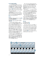
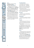
ASSIGN Point Before: TALKBACK switch Point After: (per switch): AUX 1-4, AUX 5-8, EXTERNAL, L/R, MATRIX A, MATRIX B, MATRIX C and MATRIX D. Engage the switches for locations you want to receive TALKBACK (or OSCILLATOR) signals. For instance, if your stage monitors are being fed by AUX SEND MASTERS 1-4 and you want to talk to the talent, leave the AUX 1-4 switch engaged, and toggle the TALKBACK switch on and off as needed. You can use the EXTERNAL switch to deliver the TALKBACK (and OSCILLATOR) signal to a second console, such as a monitor console. Simply patch from the FOH (front-ofhouse) console's TALKBACK output to a line-level Channel input of the monitor console. Then use that Channel's aux sends to deliver the TALKBACK signals to the stage monitors. OSCILLATOR SECTION The SR40•8's TALKBACK signal may be replaced by either of two on-board sound sources - a 400Hz sine wave for checking levels, or a PINK NOISE generator for quickly checking the frequency response of your amp/speaker systems. 400HZ/PINK NOISE Point Before: 400Hz and PINK NOISE oscillators. Point After: LEVEL (OSCILLATOR) . With the switch up (disengaged), the oscillator delivers a 400Hz sine wave, typically used for calibrating and matching levels with external devices. With the switch down (engaged), it delivers a modified PINK NOISE. PINK NOISE is used for performing quick frequency response checks. If your talent is performing that Beatles' classic, "I Want You (She's So Heavy)," you can use the PINK NOISE along with the oscillator LEVEL control to emulate that horrendous ocean sound that builds up and takes over towards the end. LEVEL Point Before: 400HZ/PINK NOISE switch. Point After: ON (OSCILLATOR) switch. This controls the signal level of all OSCILLATOR signals, be it the 400Hz sine wave or the PINK NOISE generator. The signal is off when turned fully counterclockwise, with plenty of gain turned fully clockwise. In 400Hz sine mode, you may want to send out a calibrated level (via the TALKBACK ASSIGN switches.) To do this, engage the appropriate ASSIGN switch, then engage one SOLO switch in the selected circuit. For instance, to calibrate while sending out to AUX SEND MASTER 1-4, engage the TALKBACK ASSIGN: AUX 1-4 switch and then engage SOLO on one (and only one) of those AUX SEND MASTERS. The OSCILLATOR level appears on the CENTER (PFL) Meter. Be aware: This does not mean that all outputs delivering the sine wave are calibrated, as their levels may be dependent on their own master level controls. But it does mean that the sine wave level is calibrated as it's fed to its ASSIGN switches. The PINK NOISE/400HZ oscillator cannot be assigned directly to the CENTER MAIN output . One easy way to accomplish this is to connect a patch cable between the TALKBACK OUT jack on the rear panel and the left input of one of the MAIN AUX RETURNS , A1 for example. Press EXTERNAL in the TALKBACK ASSIGN section, and assign AUX RETURN A1 to the center channel. Alternatively, AUX RETURN B4 can be used, since it is specifically assigned to the center channel. OO OO OO OO OO MAX RECEIVE IGNORE CALL COMMUNICATIONS MAX LEVEL ON 400Hz PINK NOISE OSCILLATOR TALKBACK MIC MAX TALKBACK LEVEL MATRIX A AUX 1-4 MATRIX B AUX 5-8 MATRIX C EXTERNAL MATRIX D L/R ASSIGN TALKBACK MAX SOLO LEVEL MAX PHONES INTERCOM TALKBACK CO C OS 39
-
 1
1 -
2
-
3
-
4
-
5
-
6
-
7
-
8
-
9
-
10
-
11
-
12
-
13
-
14
-
15
-
16
-
17
-
18
-
19
-
20
-
21
-
22
-
23
-
24
-
25
-
26
-
27
-
28
-
29
-
30
-
31
-
32
-
33
-
 34
34 -
 35
35 -
 36
36 -
 37
37 -
 38
38 -
 39
39 -
 40
40 -
 41
41 -
 42
42 -
 43
43 -
 44
44 -
45
-
46
-
47
-
48
-
49
-
50
-
51
-
52
-
53
-
54
-
55
-
56
-
57
-
58
-
59
-
60
-
61
-
62
-
63
-
64
-
65
-
66
-
67
-
68
-
69
-
70
-
71
-
72
-
73
-
74
-
75
-
76
-
77
-
78
-
79
-
80
-
81
-
82
-
83
-
84
-
85
-
86
 |
 |
