Magnavox 27PT91B User manual, English (US) - Page 39
Press the M. MEDIA button
 |
View all Magnavox 27PT91B manuals
Add to My Manuals
Save this manual to your list of manuals |
Page 39 highlights
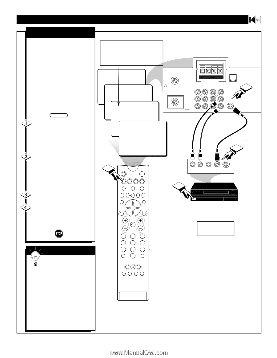
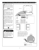
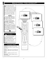
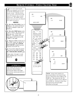
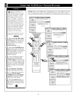
SOUND - USING THE AUDIO/VIDEO INPUT JACKS (CONT'D) S-VIDEO INPUT The S(uper)-Video connection on the rear of the TV can provide you with better picture detail and clarity for the playback of accessory sources such as DBS (digital broadcast satellite), DVD (digital video discs), video games, and S-VHS VCR (video cassette recorder) tapes than the normal antenna picture connections. NOTE: The accessory device must have an S-VIDEO OUT(put) jack in order for you to complete the connection on this page. BEGIN Connect the S-VIDEO CABLE to the S-VIDEO input jack on the rear of the television. Then connect the AUDIO (red and white) cables to the AUDIO AV2 jacks on the rear of the TV. Connect the S-VIDEO CABLE to the S-VIDEO output jack on the accessory device. Then connect the red and white AUDIO cables to the AUDIO (left and right) output jacks on the rear of the accessory device. Turn the accessory device ON. Press the M. MEDIA button on the remote control to tune the AV2 channel. You are now ready to view the tape or disc on the TV. SMART HELP The S-VIDEO and VIDEO AV2 in(puts) are in parallel. The S-VIDEO input is dominant when in use. If separate video signals are connected to the S-VIDEO and VIDEO AV2 in(puts), the signal from the VIDEO AV1 in(put) will not be usable. If you have added AV2 in(puts) to the TV's channel memory, just press the CHANNEL (+) or (-) button until the AV2 in(puts) (channel) mode is selected. NOTE: Repeatedly pressing the M. MEDIA button on the remote will toggle the picture source from the current channel, the last viewed channel, then the AV1 (or CVI) connection, the AV2 connection, and the AV3 connection. Use AV2 for S-Video Connections. 24 AV3 AV2 AV1 4 TUNER A/B POWER VCR+ M.MEDIA /RECORD M-LINK INCR.SURR. PROG. LIST OK M-LINK SOURCE OPEN/CLOSE SWAP PIP CH SOURCE FREEZE DN UP SOUND PICTURE BLUE STATUS/ EXIT GREEN GUIDE/TV INFO VOL CH MUTE 123 456 789 A/CH 0 CC SURF PIP ON/OFF ITR/ RECORD HOME VIDEO HOME PERSONAL MOVIES BACK OF TV 8 8 PIP ANT "B" 75‰ +R- -L+ M-Link SURROUND SOUND Monitor out AV1 in AV2 in 1 ANT "A" VIDEO 75‰ Y L Pb AUDIO R G-Link Pr S-VIDEO AUDIO IN (RED/WHITE) S-VIDEO CABLE (NOT SUPPLIED) 2 L R AUDIO OUT VIDEO OUT S-VIDEO ANT/CABLE OUT OUT BACK OF ACCESSORY 3 DBS, DVD, Video Game, etc. (EQUIPPED WITH S-VIDEO AND AUDIO OUTPUT JACKS) NOTE: If you are using a nonstereo device, use only the Audio R jack. 39
-
 1
1 -
2
-
3
-
4
-
5
-
6
-
7
-
8
-
9
-
10
-
11
-
12
-
13
-
14
-
15
-
16
-
17
-
18
-
19
-
20
-
21
-
22
-
23
-
24
-
25
-
26
-
27
-
28
-
29
-
30
-
31
-
32
-
33
-
 34
34 -
 35
35 -
 36
36 -
 37
37 -
 38
38 -
 39
39 -
 40
40 -
 41
41 -
 42
42 -
 43
43 -
 44
44 -
45
-
46
-
47
-
48
-
49
-
50
-
51
-
52
-
53
-
54
-
55
 |
 |