Magnavox 27PT91B User manual, English (US) - Page 45
Onnections
 |
View all Magnavox 27PT91B manuals
Add to My Manuals
Save this manual to your list of manuals |
Page 45 highlights
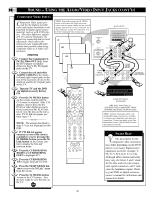
PIP - BASIC CONNECTIONS Picture-In-Picture (PIP) is the showing of two pictures on the TV screen at the same time (one main screen picture and one small picture, or PIP). For your ease and convenience, this TV has two separate inputs (ANTenna A and PIP ANTenna B) for your home's Antenna and/or Cable TV system signal. The ANT A input is primarily for the TV' s main screen picture. The PIP ANT B input is provided as a second dedicated source option for the TV's PIP "window" and its feature operations. The signal connected to the PIP ANT B input can be either a split signal input (as described in the section on this page) or another type of external signal source (such as a satellite dish system, additional home antenna, video accessory, etc.). See the following steps on how channels connected to the PIP ANT(enna) B Input can be shown and used within the PIP window. BEGIN Connect your Antenna or Cable TV signal to the single, 75-ohm input plug on a two-way signal splitter (not supplied). Connect two lengths of RF coaxial cable (F-type connectors on both ends) to the two output plugs on the two-way signal splitter. Connect the twin OUTPUT plugs on the signal splitter to the ANT A and PIP ANT B inputs on the rear of the TV. MAIN SCREEN PICTURE PIP PICTURE 300- TO 75-OHM ADAPTER COMBINATION VHF/UHF ANTENNA BACK OF TV TWIN LEAD WIRE ROUND CABLE (75 OHM) 1 NOTE: An outdoor or indoor antenna can be used to receive normal broadcast channels 2-13 (VHF) and 14-69 (UHF) 2 PIP ANT "B" 75‰ ANT "A" 75‰ 8 8 +R- -L+ SURROUND SOUND M-Link Monitor out VIDEO L AUDIO R AV1 in AV2 in Y Pb S-VIDEO Pr ANT(enna) "B" PIP ANT "B" 75‰ 8 8 +R- -L+ SURROUND SOUND M-Link OPTIONAL TWO-WAY SIGNAL SPLITTER with RF coaxial connecting cables ANT "A" 75‰ Monitor out AV1 in AV2 in VIDEO 3Y L Pb AUDIO R G-Link Pr S-VIDEO ANT(enna) "A" SMART HELP For other possible PIP connections see the "More Connections" section on pages 50-51. If you need any accessories or parts to complete the described PIP connections, contact your dealer, or call our Parts Information Center at: 1-800-851-8885 CABLE TV SIGNAL ROUND CABLE (75 OHM) CABLE TV COMPANY NOTE: The purpose of the PIP ANT B input is to provide an easily connected, dedicated picture source for PIP feature use. Other signal source options (such as a satellite dish system, an additional external antenna, a VCR, or a video game) also could be connected and displayed on the TV's PIP screen window through the use of the PIP ANT B input. 45
-
 1
1 -
2
-
3
-
4
-
5
-
6
-
7
-
8
-
9
-
10
-
11
-
12
-
13
-
14
-
15
-
16
-
17
-
18
-
19
-
20
-
21
-
22
-
23
-
24
-
25
-
26
-
27
-
28
-
29
-
30
-
31
-
32
-
33
-
34
-
35
-
36
-
37
-
38
-
39
-
 40
40 -
 41
41 -
 42
42 -
 43
43 -
 44
44 -
 45
45 -
 46
46 -
 47
47 -
 48
48 -
 49
49 -
 50
50 -
51
-
52
-
53
-
54
-
55
 |
 |
