Magnavox MS3252S User manual, English (US) - Page 21
Sing
 |
View all Magnavox MS3252S manuals
Add to My Manuals
Save this manual to your list of manuals |
Page 21 highlights
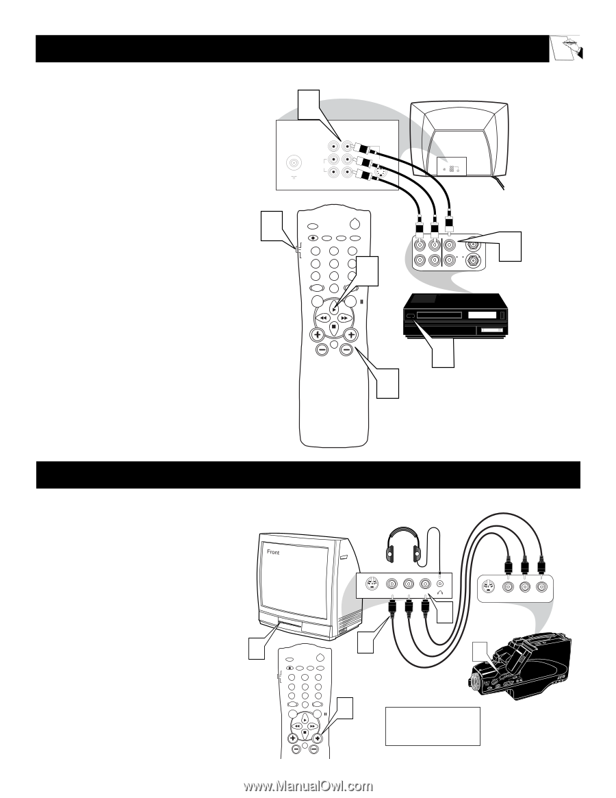
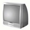
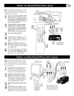
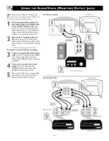
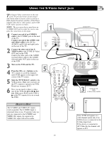
USING THE AUDIO/VIDEO INPUT JACKS Let's Look Inside! The TV's Audio/Video Input jacks are for direct picture and sound connections between the TV and a VCR (or similar accessory device) that has Audio/Video Output jacks. 1 Connect one end of the VIDEO (yellow) cable to the AV1 in VIDEO jack on the back of the TV. Then connect one end of the AUDIO (red and white) cables to the AV1 in AUDIO L and R(left and right) jacks on the rear of the TV. 2 Connect the other end of the VIDEO (yellow) cable to the VIDEO OUT jack on the back of the VCR. Then connect the other ends of the AUDIO (red and white) cables to the AUDIO (left and right) OUT jacks on the rear of the VCR. 3 Turn on the VCR and the TV. 4 Press the CH + or - button on the TV's remote to scroll the channels until AV1 appears in the upper left corner of the TV screen. 5 Slide the TV/VCR/ACC switch to the VCR position. Make sure you have set the TV's remote to operate your VCR. Details are on pages 28-33. 6 Now you are ready to place a videotape in the VCR and press the ᮣ button. (Either press PLAY on the VCR or ᮣ on the TV's remote if it is set to work the VCR.) 1 BACK OF TV 75 ⍀ Monitor out AV1 in VIDEO L/ Mono AUDIO R S-VIDEO 75 ⍀ Monitor out AV1 in VIDEO L/ Mono AUDIO R S-VIDEO 5 AUDIO IN (RED/WHITE) SLEEP POWER A/CH STATUS/EXIT CC CLOCK TV RECORD TV/VCR 1 VCR 2 3 ACC 6 4 5 6 789 SMART SMART 0 SOUND PICTURE MENU SURF OUT R AUDIO L IN VIDEO IN (YELLOW) OUT ANTENNA IN VIDEO ANTENNA OUT 2 IN BACK OF VCR VOL CH MUTE 4 3 VCR (EQUIPPED WITH VIDEO AND AUDIO OUTPUT JACKS) USING THE SIDE AUDIO/VIDEO INPUT JACKS Audio and Video Side Inputs are available for a quick connection of a VCR, to playback video from a camera or attach a gaming device. Use the AV button on the remote control to tune these inputs. 1 Connect the video (yellow) cable from the Video output on the Camera (or accessory device) to the Video (yellow) Input located on the SIDE of the TV. 2 Connect the audio cable (red and white) from the Audio Left and Right Outputs on the Camera to a Stereo to Mono adapter. Then plug the single end of the adapter to the Audio In (white) jack on the SIDE of the television. 3 Turn the TV and the accessory device ON. 4 Press the CH + or - buttons to scroll the channels until Front appears in the upper left corner of the screen. Start the playback or use of the accessory device. Jack Panel located on the Side of TV Optional Headphones Audio Cables (red & white) 3 SLEEP POWER A/CH STATUS/EXIT CC CLOCK TV RECORD 1 VCR 2 ACC 45 TV/VCR 3 6 789 SMART SMART 0 SOUND PICTURE MENU SURF VOL CH MUTE 21 S-VIDEO VIDEO L AUDIO R 2 S-VIDEO VIDEO L AUDIO R Jack Panel of Accessory Device 1 3 Video Cable (yellow) 4 When headphones re used the sound coming from the TV speakers will be mute.
-
 1
1 -
2
-
3
-
4
-
5
-
6
-
7
-
8
-
9
-
10
-
11
-
12
-
13
-
14
-
15
-
 16
16 -
 17
17 -
 18
18 -
 19
19 -
 20
20 -
 21
21 -
 22
22 -
 23
23 -
 24
24 -
 25
25 -
 26
26 -
27
-
28
-
29
-
30
-
31
-
32
-
33
-
34
-
35
-
36
-
37
-
38
-
39
-
40
 |
 |