Magnavox MS3252S User manual, English (US) - Page 23
Helpful Hint
 |
View all Magnavox MS3252S manuals
Add to My Manuals
Save this manual to your list of manuals |
Page 23 highlights
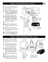
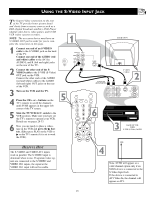
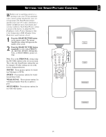
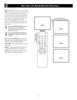
USING THE S-VIDEO INPUT JACK Let's Look Inside! The S(uper)-Video connection on the rear of the TV provides better picture detail and clarity from accessory sources such as a DBS (digital broadcast satellite), DVD Player (digital video discs), video games, and S-VHS VCR (video cassette recorder). NOTE: The accessory device must have an S-VIDEO OUT jack in order for you to complete the connection on this page. 1 Connect one end of an S-VIDEO cable to the S-VIDEO jack on the back of the TV. Connect one end of the AUDIO (red and white) cables to the AV1 In AUDIO L and R (left and right) jacks on the rear of the TV. 2 Connect the other end of the SVIDEO cable to the S-VHS (S-Video) OUT jack on the VCR. Connect the other ends of the AUDIO (red and white) cables to the AUDIO (left and right) OUT jacks on the rear of the VCR. 3 Turn on the VCR and the TV. 4 Press the CH + or - buttons on the TV's remote to scroll the channels until SVHS appears in the upper left corner of the TV screen. 5 Slide the TV/VCR/ACC switch to the VCR position. Make sure you have set the TV's remote to operate your VCR. Details are on pages 28-33. 6 Now you are ready to place a videotape in the VCR and press the ᮣ button. (Either press PLAY on the VCR or ᮣ on the TV's remote if it is set to work the VCR.) HELPFUL HINT The S-VIDEO and VIDEO AV1 inputs work in parallel. The S-VIDEO input is dominant when in use. If separate video signals are connected to the S-VIDEO and VIDEO AV1 inputs, the signal at the VIDEO AV1 input will not be usable. 1 BACK OF TV 75 ⍀ 5 Monitor out AV1 in VIDEO L/ Mono AUDIO R S-VIDEO 75 ⍀ Monitor out AV1 in VIDEO L/ Mono AUDIO R S-VIDEO AUDIO IN (RED/WHITE) OUT S-VIDEO CABLE 2 OUT S-VHS SLEEP POWER A/CH STATUS/EXIT CC CLOCK TV RECORD TV/VCR 1 VCR 2 3 ACC 6 4 5 6 789 SMART SMART 0 SOUND PICTURE MENU SURF R AUDIO L VIDEO IN IN ANTENNA IN ANTENNA OUT 3 BACK OF VCR WITH S-VHS (S-Video) JACKS VOL CH MUTE SVHS 4 Note: SVHS will appear as a valid channel option only if an SVHS device is connected to the S-Video Input Jack. If the device is connected to AV1 Video In, the channel will appear as AV1. 23
-
 1
1 -
2
-
3
-
4
-
5
-
6
-
7
-
8
-
9
-
10
-
11
-
12
-
13
-
14
-
15
-
16
-
17
-
 18
18 -
 19
19 -
 20
20 -
 21
21 -
 22
22 -
 23
23 -
 24
24 -
 25
25 -
 26
26 -
 27
27 -
 28
28 -
29
-
30
-
31
-
32
-
33
-
34
-
35
-
36
-
37
-
38
-
39
-
40
 |
 |
