Makita LS1216L Owners Manual - Page 10
Assembly - compound miter saw
 |
View all Makita LS1216L manuals
Add to My Manuals
Save this manual to your list of manuals |
Page 10 highlights
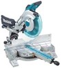
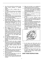
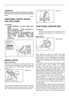
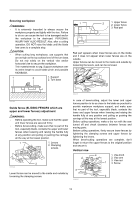
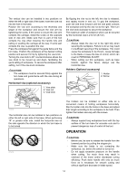
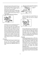
center for proper repairs BEFORE further usage. • NEVER tape down or defeat purpose and function of lock-off button. Electric brake This tool is equipped with an electric blade brake. If the tool consistently fails to quickly stop blade after switch trigger release, have tool serviced at a Makita service center. The blade brake system is not a substitute for blade guard. NEVER USE TOOL WITHOUT A FUNCTIONING BLADE GUARD. SERIOUS PERSONAL INJURY CAN RESULT. Electronic function Constant speed control • Possible to get fine finish, because the rotating speed is kept constantly even under the loaded condition. Soft start feature • Soft start because of suppressed starting shock. Laser beam action For model LS1216L only 1. Switch for laser 1. Loosen the adjusting screw by turning it counterclockwise. 2. With the adjusting screw loosened, slide the adjusting screw to the right or left as far as it goes. 3. Tighten the adjusting screw firmly at the position where it stops sliding. Laser line is factory adjusted so that it is positioned within 1 mm (0.04") from the side surface of the blade (cutting position). NOTE: • When laser line is dim and almost or entirely invisible because of the direct sunlight in the indoor or outdoor window-by work, relocate the work area to a place not exposed to the direct sunlight. Aligning the laser line A B 009494 1 009492 CAUTION: • LASER RADIATION Do not stare into beam. To turn on the laser beam, press the upper position (I) of the switch. Press the lower position (O) to turn off. Laser line can be shifted to either the left or right side of the saw blade by adjusting the adjusting screw as follows. 1. Adjusting screw 1 Laser line can be shifted to either the left or right side of the blade according to the applications of cutting. Refer to explanation titled "Laser beam action" regarding its shifting method. NOTE: • Use wood facing against the guide fence when aligning the cutting line with the laser line at the side of guide fence in compound cutting (bevel angle 45 degrees and miter angle right 45 degrees). A) When you obtain correct size on the left side of workpiece • Shift the laser line to the left of the blade. B) When you obtain correct size on the right side of workpiece • Shift the laser line to the right of the blade. Align the cutting line on your workpiece with the laser line. ASSEMBLY 009493 CAUTION: • Always be sure that the tool is switched off and unplugged before carrying out any work on the tool. 10
-
 1
1 -
2
-
3
-
4
-
 5
5 -
 6
6 -
 7
7 -
 8
8 -
 9
9 -
 10
10 -
 11
11 -
 12
12 -
 13
13 -
 14
14 -
 15
15 -
16
-
17
-
18
-
19
-
20
-
21
-
22
-
23
-
24
-
25
-
26
-
27
-
28
-
29
-
30
-
31
-
32
-
33
-
34
-
35
-
36
-
37
-
38
-
39
-
40
-
41
-
42
-
43
-
44
-
45
-
46
-
47
-
48
-
49
-
50
-
51
-
52
-
53
-
54
-
55
-
56
-
57
-
58
-
59
-
60
-
61
-
62
-
63
-
64
-
65
-
66
-
67
-
68
-
69
-
70
-
71
-
72
-
73
-
74
-
75
-
76
-
77
-
78
-
79
-
80
-
81
-
82
-
83
-
84
 |
 |
