Makita LS1216L Owners Manual - Page 16
Miter cutting, Bevel cut, CAUTION, Compound cutting, Cutting crown and cove moldings
 |
View all Makita LS1216L manuals
Add to My Manuals
Save this manual to your list of manuals |
Page 16 highlights
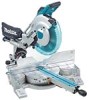
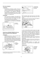
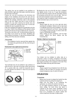
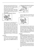
3. Miter cutting Refer to the previously covered "Adjusting the miter angle". 4. Bevel cut 5. Compound cutting Compound cutting is the process in which a bevel angle is made at the same time in which a miter angle is being cut on a workpiece. Compound cutting can be performed at angle shown in the table. Miter angle Left and Right 0 - 45 009713 Bevel angle Left and Right 0 - 45 009505 Loosen the lever and tilt the saw blade to set the bevel angle (Refer to the previously covered "Adjusting the bevel angle"). Be sure to retighten the lever firmly to secure the selected bevel angle safely. Secure the workpiece with a vise. Make sure the carriage is pulled all the way back toward the operator. Switch on the tool without the blade making any contact and wait until the blade attains full speed. Then gently lower the handle to the fully lowered position while applying pressure in parallel with the blade and PUSH THE CARRIAGE TOWARD THE GUIDE FENCE TO CUT THE WORKPIECE. When the cut is completed, switch off the tool and WAIT UNTIL THE BLADE HAS COME TO A COMPLETE STOP before returning the blade to its fully elevated position. CAUTION: • Always be sure that the blade will move down to bevel direction during a bevel cut. Keep hands out of path of saw blade. • During a bevel cut, it may create a condition whereby the piece cut off will come to rest against the side of the blade. If the blade is raised while the blade is still rotating, this piece may be caught by the blade, causing fragments to be scattered which is dangerous. The blade should be raised ONLY after the blade has come to a complete stop. • When pressing down the handle, apply pressure in parallel with the blade. If a force is applied perpendicularly to the turn base or if the pressure direction is changed during a cut, the precision of the cut will be impaired. • Before bevel-cutting, the adjustment of upper fence and lower fence is required. Refer to the section titled "Guide fence adjustment". When performing compound cutting, refer to "Press cutting", "Slide cutting", "Miter cutting" and "Bevel cut" explanations. 6. Cutting crown and cove moldings Crown and cove moldings can be cut on a compound miter saw with the moldings laid flat on the turn base. There are two common types of crown moldings and one type of cove moldings; 52/38° wall angle crown molding, 45° wall angle crown molding and 45° wall angle cove molding. See illustrations. 1. 52/38 ゚ type crown molding 2. 45 ゚ type crown 52 45 45 molding 38 45 45 3. 45 ゚ type cove molding 1 2 3 001555 There are crown and cove molding joints which are made to fit "Inside" 90° corners ((1) and (2) in Fig. A) and "Outside" 90° corners ((3) and (4) in Fig. A). 1. Inside corner 2. Outside corner Fig.A 001556 (1) (2) (3) (4) 1 2 1. Inside corner 1 (2) (1) 2. Outside corner (1) (2) (2) (1) (4) (3) 2 (2) (1) (1) (2) 001557 16
-
 1
1 -
2
-
3
-
4
-
5
-
6
-
7
-
8
-
9
-
10
-
 11
11 -
 12
12 -
 13
13 -
 14
14 -
 15
15 -
 16
16 -
 17
17 -
 18
18 -
 19
19 -
 20
20 -
 21
21 -
22
-
23
-
24
-
25
-
26
-
27
-
28
-
29
-
30
-
31
-
32
-
33
-
34
-
35
-
36
-
37
-
38
-
39
-
40
-
41
-
42
-
43
-
44
-
45
-
46
-
47
-
48
-
49
-
50
-
51
-
52
-
53
-
54
-
55
-
56
-
57
-
58
-
59
-
60
-
61
-
62
-
63
-
64
-
65
-
66
-
67
-
68
-
69
-
70
-
71
-
72
-
73
-
74
-
75
-
76
-
77
-
78
-
79
-
80
-
81
-
82
-
83
-
84
 |
 |
