Makita LS1216L Owners Manual - Page 20
Cutting aluminum extrusion, CAUTION, Wood facing
 |
View all Makita LS1216L manuals
Add to My Manuals
Save this manual to your list of manuals |
Page 20 highlights
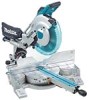
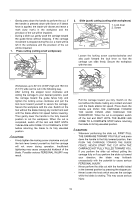
12 3 009521 12 3 1. Crown molding stopper L (Optional accessory) 2. Crown molding stopper R (Optional accessory) 3. Turn base 1. Crown molding stopper L 2. Crown molding stopper R 3. Turn base 009522 Fig. B: At right 45° miter angle Fig. C: At left 45° miter angle Position crown molding with its WALL CONTACT EDGE against the guide fence and its CEILING CONTACT EDGE against the crown molding stoppers as shown in the figure. Adjust the crown molding stoppers according to the size of the crown molding. Tighten the screws to secure the crown molding stoppers. Refer to the table (C) for the miter angle. 1. Guide fence 1 2. Crown molding 7. Cutting aluminum extrusion 1. Guide fence 1 2. Vise 2 3. Spacer block 3 4. Aluminum 4 extrusion 5 5. Spacer block 009523 When securing aluminum extrusions, use spacer blocks or pieces of scrap as shown in the figure to prevent deformation of the aluminum. Use a cutting lubricant when cutting the aluminum extrusion to prevent build-up of the aluminum material on the blade. CAUTION: • Never attempt to cut thick or round aluminum extrusions. Thick aluminum extrusions may come loose during operation and round aluminum extrusions cannot be secured firmly with this tool. 8. Wood facing Use of wood facing helps to assure splinter-free cuts in workpieces. Attach a wood facing to the guide fence using the holes in the guide fence and 6 mm (1/4") screws. See the figure concerning the dimensions for a suggested wood facing. Over 15mm(9/16") Over 290mm(11-3/8") Over 340mm(13-3/8") 80mm (3-1/8") 115 - 120mm (4-1/2" - 4-3/4") 2 009520 Table (C) Position in Fig. A Miter angle Finished piece For inside (1) corner (2) For outside (3) corner (4) 006365 Right 45° Save the right side of blade Left 45° Save the left side of blade Save the right side of blade Right 45° Save the left side of blade 1 135mm 106mm 116mm 180mm (5-5/16") (4-3/16") (4-9/16") (7-1/8") 1 1. Hole 010047 CAUTION: • Use straight wood of even thickness as the wood facing. • When cutting workpieces from 107 mm (4 -1/4") to 120 mm (4 - 3/4") high, use a wood facing to prevent a portion of the workpiece near the guide fence from being left uncut. 20
-
 1
1 -
2
-
3
-
4
-
5
-
6
-
7
-
8
-
9
-
10
-
11
-
12
-
13
-
14
-
 15
15 -
 16
16 -
 17
17 -
 18
18 -
 19
19 -
 20
20 -
 21
21 -
 22
22 -
 23
23 -
 24
24 -
 25
25 -
26
-
27
-
28
-
29
-
30
-
31
-
32
-
33
-
34
-
35
-
36
-
37
-
38
-
39
-
40
-
41
-
42
-
43
-
44
-
45
-
46
-
47
-
48
-
49
-
50
-
51
-
52
-
53
-
54
-
55
-
56
-
57
-
58
-
59
-
60
-
61
-
62
-
63
-
64
-
65
-
66
-
67
-
68
-
69
-
70
-
71
-
72
-
73
-
74
-
75
-
76
-
77
-
78
-
79
-
80
-
81
-
82
-
83
-
84
 |
 |
