Marantz PM-17SA User Guide - Page 5
Names Of Controls And Indicators - integrated amp
 |
View all Marantz PM-17SA manuals
Add to My Manuals
Save this manual to your list of manuals |
Page 5 highlights
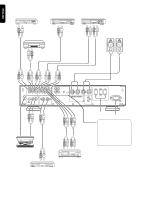
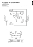
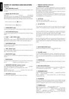
ENGLISH ENGLISH FRANCAIS FRANCÇAIS DEUTSCH DEUTSCH NEDERLANDS NEDERLANDS ESPANOL ESPAÑOL NAMES OF CONTROLS AND INDICATORS (Page 20) " GND (GROUND) terminal Connect the grounding wire from the Analog turntable to this terminal. # MM/MC SELECTOR switch When the INPUT SELECTOR is set to PHONO, the type of cartridge used on the turntable can be selected between MM (Moving Magnet) and MC (Moving Coil) using this switch. Set this switch according to the cartridge used on the turntable. MM (Moving Magnet) Set the switch to the out )position. MC (Moving Coil) Set the switch to the in ( )position. $ PHONO INPUT jacks Connect the output jacks of the Analog turntable to these jacks. % CD PLAYER INPUT jacks Connect the output jacks of a Compact Disc player to these jacks. & LINE 1 - LINE 3 INPUT jacks These are LINE 1 - LINE 3 input jacks which can be used to connect the audio outputs of AV components such as TV multiplex/stereo audio turners, VCRs, and leaserdisc players. ' CD-R IN/OUT jack Connect the line output jacks and line input jacks of CD recorder to these jacks. ( TAPE IN/OUT jacks Connect the play (output) jacks and record (input) jacks of tape decks to these jacks. ) PRE OUTPUT jacks Output jack for connection to extension power-amp, mixer or similar. * MAIN IN jacks Connect the pre-output jacks of your pre-amp to these jacks at the SEPARATE position of the selection switch +. + SEPARATE/COUPLED selection switch The initial setting of the selection switch is COUPLED position. This unit is possible to use integrated-amp at the COUPLED position. Set according to the SEPARATED position, this unit is possible to use pre-amp or power-amp. , SPEAKER terminals Connect your speaker system to these terminals. - REMOTE CONTROL BUS jacks (REMOTE CONT. BUS) By connecting this unit with a MARANTZ component equipped with the remote control (D-BUS) jacks, both components can be remote controlled as a system. For details of the remote control function, read the owner's manual of the connected component. The bus OUT terminal is used to send signals to another item of equipment. The bus IN terminal is used to receive signals from another item of equipment. . AC IN jack Connect to AC power outlet. This unit can be powered by 120V AC only. / AC OUTLETS [SWITCHED] The switched outlet is turned on and off by the main power switch. The maximum power capacity of this outlet is 120W. [UNSWITCHED] Use this outlet as the power supply for a component that does not need to be turned on and off by the main power switch. The maximum power capacity of this outlet is 120W. Do not plug a device that consumes a great deal of power into this outlet. For the best audio quality, we recommend that you plug your CD player, MD player, or other digital audio component into a power outlet that is independent of the power supply for the amp. q INPUT SELECTOR switch Selects the program source to be produced, from PHONO, CD, LINE 1, LINE 2, LINE 3,CD-R and TAPE. w VOLUME control Turn the knob to adjust the volume. Turning the knob clockwise ( ) to increase the volume. The volume up-down operations can also be controlled from the provided remote control unit. e PHONES jack This jack accepts the standard stereo phone plug of headphones. r REC SELECTOR switch Selects the COPY mode between CD recorder and TAPE deck, or the signal to be output to the OUT jacks of CD-R and TAPE. t SPEAKERS switch Press to switch the speaker systems ON (pressed-in position) and OFF (out position). Set the switch to OFF (out position) when you listen through headphones only. y IR SENSOR The unit receives the infrared remote control signal through this window. Point the transmitter of the remote control unit toward this window to send correct remote control signals. u POWER switch Press to turn power ON and press again to turn it OFF. Meter !1 lights up when the POWER is turned ON. The pointer LED of the INPUT SELECTOR switch q also lights when the power is ON and goes out when it is OFF. This switch also switches O/OFF the power supply from the AC OUTLETS (SWITCHED) on the rear panel. ITALINO ITALINO PORTUGUES PORTUGUÊS SVENSKA SVENSKA DANSK DANSK 4
-
 1
1 -
 2
2 -
 3
3 -
 4
4 -
 5
5 -
 6
6 -
 7
7 -
 8
8 -
 9
9 -
 10
10 -
 11
11 -
12
-
13
 |
 |
