

Service Manual - Page 1
Customer Service
TM
Washer Service Manual
16010061
Compiled From
16008373, 16010199, 16010886 11/03
Service Manual - Page 2
SAFETY PRECAUTIONS
This manual is to be used only by a Maytag Authorized Service Technician familiar with and knowledgeable of proper safety and servicing procedures and possessing high quality testing equipment associated with microwaves, gas, and electrical appliance repair. All individuals who attempt repairs by improper means or adjustment subject themselves and others to the risk of serious or fatal injury.
USE ONLY GENUINE MAYTAG APPROVED FACTORY REPLACEMENT COMPONENTS.
16008373-01
© 1998 Maytag Corporation
SAFETY PRECAUTIONS
Service Manual - Page 3
INTRODUCTION
Each model will be covered separately in a section pertaining only to its control system and internal components. Because the basic structure for all washers is the same, they will be covered generally without regard to model.
Model(s) covered in this manual:
MAH3000
For additional information on material covered in this manual, including safety issues, contact:
Maytag Appliances Sales Company 240 Edwards Street, S.E. Cleveland, TN 37311 Phone: 423.472.3333 FAX: 423.478.6722
16008373-01
© 1998 Maytag Corporation
INTRODUCTION
i
Service Manual - Page 4
...T S ...i i
SECTION 1. GENERAL INFORMATION ...1 - 1 PRE-INSTALLATION REQUIREMENTS ...1 - 1 U N C R A T I N G ...1 - 1 I N S T A L L A T I O N...1 - 2 GROUNDING POLARITY CHECKS ...1-4 S P E C I F I C A T I O N S ...1-4 WASHER CONTROLS ...1 - 5 INPUT DEFINITIONS ...1 - 6 OUTPUT DEFINITIONS ...1 - 8 CYCLE SEQUENCE DEFINITIONS ...1 - 1 0 M I S C E L L A N E O U S ...1 - 1 1
Door Latch Switch Monitoring ...1 - 1 1 Door Lock/Spin Control ...1 - 1 1 Redistribution ...1 - 1 1 Push-To-Start... Sensor ...2 - 1 3 Cabinet Vibration Absorber ...2 - 1 3
16008373-01
© 1998 Maytag Corporation
CONTENTS
ii
Service Manual - Page 5
... Not Spin ...3-6 Machine Stalls During Spin ...3-8 Maximum Spin Speed Is Not Reached 3-9 Wash Cycle Takes Longer Than Normal 3 - 1 0 Suds Coming Out Of Door ...3 - 1 0 Washer Will Not Start ...3 - 1 1 Motor Phase Test ...3 - 1 2 TIMER TEMPLATE OVERLAY ...3 - 1 3 MISCELLANEOUS INFORMATION ...3-14
SECTION 4. CONSOLE ...4 - 1 R E M O V A L ...4-1 VERTICAL SWITCHES...4-2 HORIZONTAL SWITCHES... A F F L E S ...7 - 1 DOOR BOOT ...7 - 1 OUTER TUB COVER ...7-2 SPIN BASKET ASSEMBLY W/BALANCE RING 7-3 DRIVE PULLEY ...7-4 SPINNER TUB SUPPORT ...7-5
16008373-01
©1997 Maytag Corporation
CONTENTS iii
Service Manual - Page 6
... Prior to Series 17 ...9-2 Schematic Series 17 ...9-3 Timer Chart Series 17 ...9-4 Schematic Series 18 ...9-5 Timer Chart Series 18 ...9-6 Schematic Series 19 ...9-7
16008373-01
© 1998 Maytag Corporation
CONTENTS
iv
Service Manual - Page 7
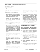
...washer.
• Hot and Cold water faucets must be within four (4) feet of the back of the washer... C) hot water to the washer.
• Do not store or operate washer in temperatures below freezing. This...8226; Best performance is obtained with the washer installed on a solid floor. Wood floor...movement during the spin cycle. Never install washer on a platform or weak support structure...to the washer.
2. Carefully remove any packaging materials from the outside of the washer. IMPORTANT:...washer by removing crate bottom wire clips.
• Water pressure of 20 - 120 P.S.I. is required to fill the washer...
Service Manual - Page 8
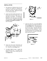
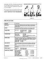
...extending up through the bottom of the base (Figure 1-4). The shipping bolts are near the center of the base toward the front of the washer. Remove both bolts, freeing the tub and suspension. Do not be alarmed should the tub assembly shift when the last bolt is removed. Some... normal.
Figure 1-1
B. Grasp each loose strap individually and pull the strap to remove it from the cabinet. Discard the strap (Figure 1-2).
2. Tip washer slightly forward. Loosen rear leveling leg lock nuts. Tip washer back slightly to loosen front leveling leg lock nuts (Figure 1-3).
Figure 1-3
16008373-01
© 1998...
Service Manual - Page 9
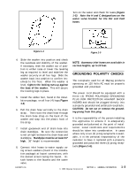
... hose and standpipe. Standpipe must be at least 24" high. 36" height is recommended.
8. Connect inlet hoses to water supply using screen washers (found in the installation package) at faucet connections, with the domed screen facing the faucet. Attach hoses to the faucets and the water valve....
NOTE: Accessory inlet hoses are available in various lengths, up to 10 feet.
GROUNDING POLARITY CHECKS
The receptacle used for all Maytag products operating on 120 Volts AC must be properly grounded and polarized.
The power cord should be equipped with a three (3) PRONG POLARIZED GROUNDING...
Service Manual - Page 10
... basket w ith no clothes, m easured near the rear seam of the spin basket. WASH LEVEL 3-4 inches RINSE LEVEL 4-5 inches
Four-foot inlet hoses w ith inlet washers and attaches to water valv e. Dr ain hose attaches to pump and w ill accomm odate 36" dr ain stand p i p e.
Cabinet dimensions: 27" (68.58cm) W x 27... 7in. lbs
(± 3in.lbs) (± 3in. lbs) (± 10in. lbs) (± 3in. lbs) (± 3in. lbs)
(± 3in. lbs) (± 3in. lbs)
© 1998 Maytag Corporation
SECTION 1. GENERAL INFORMATION
1-4
Service Manual - Page 11
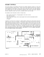
...motor. - On Light.
In general, the timer dial is rotated to a desired setting, selects the cycles options using the option switches, and starts the washer. The machine control reads the inputs from the timer, option switches and pressure switch then send output signals to the motor control and other components... from the timer, and acts upon them. This continues until the cycle is complete. (See Figure 1-7 & 1-8 for a generic representation of the Neptune washer control system.)
Figure 1-7
16008373-01
Prior To Series 17
© 1998 Maytag Corporation
SECTION 1. GENERAL INFORMATION
1-5
Service Manual - Page 12
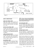
... 17 & Later
INPUT DEFINITIONS
DOOR LOCK SWITCH INPUT When input is present, this is indication the washer door is locked. The machine controller will not command the spinner to spin faster than 50 rpm ...user input switch on the control panel. The machine control reads these inputs to determine which cycles should be run when the washer is started.
MAX EXTRACT INPUT The Max Extract Input is energized through a user input switch on the control panel. When... water valves is no longer passed to the machine control. The
16008373-01
© 1998 Maytag Corporation
SECTION 1. GENERAL INFORMATION
1-6
Service Manual - Page 13
...direction but does not sense a tach input signal within five seconds, it will disengage the line relay to stop the washer. This generally indicates a locked rotor or a malfunction in the motor control.
If the machine control senses a tach ...but is still receiving a tach input signal after two minutes, it will disengage the line relay to stop the washer.
TEMPERATURE SENSOR INPUT A thermistor is located in the water valve to monitor the blended incoming water temperature. The... for each fill (See Water Valve Outputs).
16008373-01
© 1998 Maytag Corporation
SECTION 1. GENERAL INFORMATION
1-7
Service Manual - Page 14
...in the door lock assembly. The wax motor extends to drive the door lock system for the washer.
If the washer is started with the timer set in a Prewash Tumble, Main Wash Tumble, or Light Wash ...the appropriate level. The Timer Motor Output is disengaged during this time.
The machine control will stop the washer by disengaging the line relay if the following occur: 1) The machine control energizes the timer motor until ... final (Spin 3) sequence until 30 seconds before the washer begins to coast from the final speed.
16008373-01
© 1998 Maytag Corporation
SECTION 1. GENERAL INFORMATION
1-8
Service Manual - Page 15
.../ Perm Press fabric selection, all rinse fills will be cold regardless of whether the user also selected the warm rinse temperature.
16008373-01
© 1998 Maytag Corporation
SECTION 1. GENERAL INFORMATION
1-9
Service Manual - Page 16
... increment into the Rinse Tumble increment.
washers only) will de-energize and the ...TUMBLE The machine control will tumble the washer at the pattern and speed defined by... machine control will continue to tumble the washer until the timer inputs change.
In ...will de-energize the line relay if the washer continues to tumble for 29 minutes. This...PREWASH DRAIN During a prewash drain increment, the washer will tumble at the same speed and in... the machine control will tumble the washer until 50 seconds after the Door... At this time, the Door Lock Light Output (washers between Series 10 and 16 only) or the ...
Service Manual - Page 17
...Door Lock/Spin Control
control will energize the timer motor output until the timer inputs change so the washer can proceed with the cycle.
At the end of spin sequence, if the door lock switch input is de-energized... ramp from 0 rpm to 85 rpm at the beginning of each high speed (above 100 rpm) spin. When the washer reaches 85 rpm, the machine control monitors the Tach Input to determine if the speed varies through one revolution of the ... lock switch is not energized after 2 minutes of tumbling, the machine
16008373-01
© 1998 Maytag Corporation
SECTION 1. GENERAL INFORMATION
1-11
Service Manual - Page 18
...skips the step and continues with the spin profile (See Section 2: Unbalance Control System).
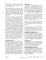
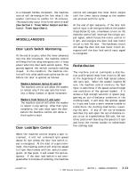
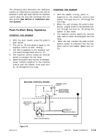
Push-To-Start Relay Operation
STARTING THE WASHER
1. With the door closed, press the push-to start switch.
2. The red no. 28 wire sends a signal to ...line relay.
4. When the user releases the push-to-start button, power is removed from the machine control and washer (Black wire no. 27).
MACHINE CONTROL BOARD
LINE R EL AY
NO
COM
INTERNAL LOGIC SWITCH
120 VAC POWER ... Line To Timer & Motor Control Board
RD 28
Figure 1-8
16008373-01
© 1998 Maytag Corporation
SECTION 1. GENERAL INFORMATION
1-12
Service Manual - Page 19
... retract at the end of the cycle.
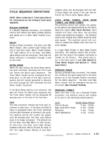
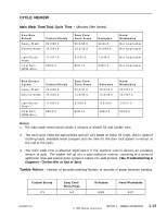
3. The main wash time is affected significantly if the machine control detects an excessive amount of suds. The washer will go into a suds reduction routine, consisting of a series of additional rinse and partial drain cycles to reduce the suds present (See Troubleshooting & Diagnosis - Clothes... - Number of seconds tumbling/Number of seconds of pause between tumbles.
Cotton/ Sturdy 7/3
Easy Care/ Perm Press
5/3
D e licat e s 6/ 2 4
Hand W ashab les 3/ 2 7
16008373-01
© 1998 Maytag Corporation
SECTION 1. GENERAL INFORMATION
1-13
Service Manual - Page 21
SECTION 2. ELECTRICAL COMPONENTS & TESTING
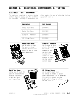
ELECTRICAL TEST EQUIPMENT
The equipment required to service Maytag products depends largely upon the conditions you encounter. Locating a malfunction will
often require the use of electrical testing equipment such as:
Description Analog Test Meter ....
Clamp-On Ammeter can be used to detect shorts. Overloads on the circuit breaker or fuse can be traced to either the washer or circuit breaker by checking the washer current draw.
Digital Test Meter can be used to check for open or closed circuits, measure resistance, AC and DC volts, and...