Maytag MAH5500BWW Service Manual - Page 9
Grounding Polarity Checks - won t drain
 |
View all Maytag MAH5500BWW manuals
Add to My Manuals
Save this manual to your list of manuals |
Page 9 highlights
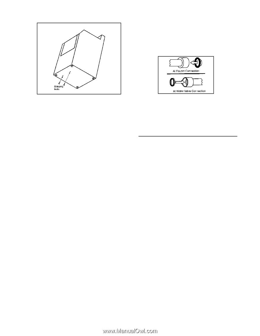
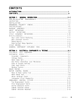
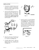
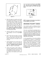
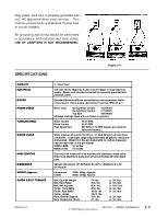
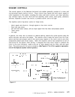
Turn on the water and check for leaks (Figure 1-5). Note the H and C designations on the water valve bracket for the Hot and Cold hoses. Figure 1-4 Figure 1-5 4. Slide the washer into position and check the levelness and stability of the washer. If necessary, slide the washer out of position to either raise or lower the leveling leg as required to level and stabilize the washer securely on all four legs. Slide the washer back into position to confirm levelness to the floor. When the washer is level, tighten the locking nuts up against the base of the washer. This will secure the leveling legs in place. 5. Install the rubber feet, found in the installation package, on all four (4) legs (Figure 1-3). 6. Pull the drain hose vertically to the drain strap . Then route the drain hose through the drain hose strap on the back of the washer and snap into the plastic hook of the strap. 7. Install gooseneck end of drain hose into drain standpipe. Be sure the connection is not airtight between the drain hose and standpipe. Standpipe must be at least 24" high. 36" height is recommended. 8. Connect inlet hoses to water supply using screen washers (found in the installation package) at faucet connections, with the domed screen facing the faucet. Attach hoses to the faucets and the water valve. NOTE: Accessory inlet hoses are available in various lengths, up to 10 feet. GROUNDING POLARITY CHECKS The receptacle used for all Maytag products operating on 120 Volts AC must be properly grounded and polarized. The power cord should be equipped with a three (3) PRONG POLARIZED GROUNDING PLUG FOR PROTECTION AGAINST SHOCK HAZARD and should be plugged directly into a properly grounded and polarized receptacle. CAUTION: Do not cut or remove the grounding prong from this plug. It is the responsibility of the person installing the appliance to ensure it is adequately grounded and polarized at the point of installation. Local conditions and requirements should be taken into consideration. In cases where only a two (2) prong receptacle is available, it is the personal responsibility of the customer to have it replaced with a properly grounded and polarized three (3) prong receptacle (Figure 1-6). 16008373-01 © 1998 Maytag Corporation SECTION 1. GENERAL INFORMATION 1-3
-
 1
1 -
2
-
3
-
 4
4 -
 5
5 -
 6
6 -
 7
7 -
 8
8 -
 9
9 -
 10
10 -
 11
11 -
 12
12 -
 13
13 -
 14
14 -
15
-
16
-
17
-
18
-
19
-
20
-
21
-
22
-
23
-
24
-
25
-
26
-
27
-
28
-
29
-
30
-
31
-
32
-
33
-
34
-
35
-
36
-
37
-
38
-
39
-
40
-
41
-
42
-
43
-
44
-
45
-
46
-
47
-
48
-
49
-
50
-
51
-
52
-
53
-
54
-
55
-
56
-
57
-
58
-
59
-
60
-
61
-
62
-
63
-
64
-
65
-
66
-
67
-
68
-
69
-
70
-
71
-
72
-
73
-
74
-
75
-
76
-
77
-
78
-
79
-
80
-
81
-
82
-
83
-
84
-
85
-
86
-
87
-
88
-
89
-
90
-
91
-
92
-
93
-
94
-
95
-
96
-
97
-
98
-
99
-
100
-
101
-
102
-
103
-
104
-
105
-
106
-
107
-
108
-
109
-
110
-
111
-
112
-
113
-
114
-
115
-
116
-
117
-
118
-
119
-
120
-
121
-
122
-
123
-
124
-
125
-
126
-
127
-
128
-
129
-
130
-
131
-
132
-
133
-
134
-
135
-
136
-
137
-
138
-
139
-
140
-
141
-
142
-
143
-
144
-
145
-
146
-
147
-
148
-
149
-
150
-
151
-
152
-
153
-
154
-
155
-
156
-
157
 |
 |