Maytag MAH5500BWW Service Manual - Page 8
Installation - shipping bolt
 |
View all Maytag MAH5500BWW manuals
Add to My Manuals
Save this manual to your list of manuals |
Page 8 highlights
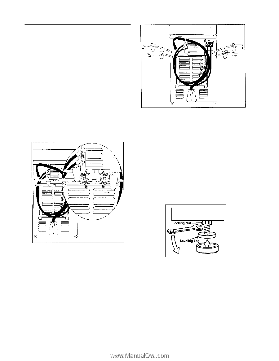
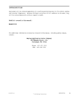
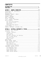
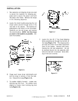
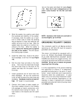
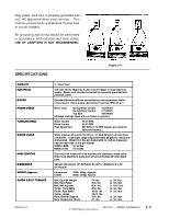
I N S TA L L AT I O N 1. Two separate red shipping straps are used to secure the machine for shipping purposes and to secure the power cord with the water inlet hoses. Remove the straps in the following sequence: A. Locate the metal buckles securing the red straps which extend through slots in the rear wall of the cabinet. The buckles are positioned in the center of the red straps. Carefully cut the red straps, and remove the metal buckles. NOTE: Cut the straps as close to the buckles as possible. Discard the buckles. Figure 1-2 3. Locate the two (2) ½" hex head shipping bolts extending up through the bottom of the base (Figure 1-4). The shipping bolts are near the center of the base toward the front of the washer. Remove both bolts, freeing the tub and suspension. Do not be alarmed should the tub assembly shift when the last bolt is removed. Some shifting of the tub is normal. Figure 1-1 B. Grasp each loose strap individually and pull the strap to remove it from the cabinet. Discard the strap (Figure 1-2). 2. Tip washer slightly forward. Loosen rear leveling leg lock nuts. Tip washer back slightly to loosen front leveling leg lock nuts (Figure 1-3). Figure 1-3 16008373-01 © 1998 Maytag Corporation SECTION 1. GENERAL INFORMATION 1-2
-
 1
1 -
2
-
 3
3 -
 4
4 -
 5
5 -
 6
6 -
 7
7 -
 8
8 -
 9
9 -
 10
10 -
 11
11 -
 12
12 -
 13
13 -
14
-
15
-
16
-
17
-
18
-
19
-
20
-
21
-
22
-
23
-
24
-
25
-
26
-
27
-
28
-
29
-
30
-
31
-
32
-
33
-
34
-
35
-
36
-
37
-
38
-
39
-
40
-
41
-
42
-
43
-
44
-
45
-
46
-
47
-
48
-
49
-
50
-
51
-
52
-
53
-
54
-
55
-
56
-
57
-
58
-
59
-
60
-
61
-
62
-
63
-
64
-
65
-
66
-
67
-
68
-
69
-
70
-
71
-
72
-
73
-
74
-
75
-
76
-
77
-
78
-
79
-
80
-
81
-
82
-
83
-
84
-
85
-
86
-
87
-
88
-
89
-
90
-
91
-
92
-
93
-
94
-
95
-
96
-
97
-
98
-
99
-
100
-
101
-
102
-
103
-
104
-
105
-
106
-
107
-
108
-
109
-
110
-
111
-
112
-
113
-
114
-
115
-
116
-
117
-
118
-
119
-
120
-
121
-
122
-
123
-
124
-
125
-
126
-
127
-
128
-
129
-
130
-
131
-
132
-
133
-
134
-
135
-
136
-
137
-
138
-
139
-
140
-
141
-
142
-
143
-
144
-
145
-
146
-
147
-
148
-
149
-
150
-
151
-
152
-
153
-
154
-
155
-
156
-
157
 |
 |