Maytag MAH5500BWW Service Manual - Page 13
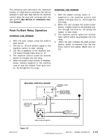
See Push-To-Start/Line Relay Operation. - motor
 |
View all Maytag MAH5500BWW manuals
Add to My Manuals
Save this manual to your list of manuals |
Page 13 highlights
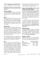
machine control interprets this loss of power as an indication that the water level has reached the full level. When the washer is at the "full" level and the timer is set in a Prewash Tumble, Main Wash Tumble, Light Wash Tumble, or Rinse Tumble increment, the machine control will begin the sequence timing defined for each cycle and fabric selection setting (See Cycle Sequence Definitions). During the drain and spin increments after the main wash, first rinse, second rinse, and extra rinse increments, the wash side circuit in the pressure switch is closed. When the water level drains below the wash full level, the circuit will close and energize the pressure switch input. The machine control interprets this signal (not to energize the water valve outputs) to measure how quickly the washer is draining. If the machine control commands a spin speed above 51 rpm before the pressure switch input is energized, it will drop the speed to 0 rpm and hold there until the pressure switch input is energized. An additional delay equal to the length of time elapsed will occur before the pressure switch input is energized. If four minutes elapse without the pressure switch input being energized, the machine control will energize the timer motor output to advance the timer into the next increment and continue with the cycle. START/STOP INPUT The start/stop input is energized by the momentary Push-to-Start/Stop Switch. If this input is energized when a cycle is in progress, the machine control will disengage the line relay, both water valve output signals, the door lock wax motor signal, the timer motor output signal, and the on-light output signal. If this input is energized when a cycle is not in progress, the machine control will energize the line relay and begin the cycle sequence as defined by the timer and user input switches (See Push-To-Start/Line Relay Operation). TACH INPUT The tach input is a feedback signal from the motor control. It provides eight pulses per revolution of the switched reluctance motor. The motor runs at 14 times the speed of the spinner (14:1 belt ratio). The tach input is used for monitoring speed and out-of-balance detection (See Tachometer Circuit Diagnostics). If the machine control commands a motor speed and direction but does not sense a tach input signal within five seconds, it will disengage the line relay to stop the washer. This generally indicates a locked rotor or a malfunction in the motor control. If the machine control senses a tach input signal when it is not commanding the motor to run, it will disengage the line relay to stop the washer. If the machine control commands a coast down from final spin speed but is still receiving a tach input signal after two minutes, it will disengage the line relay to stop the washer. TEMPERATURE SENSOR INPUT A thermistor is located in the water valve to monitor the blended incoming water temperature. The machine control uses this input signal to regulate the water temperature with the warm or cold wash or warm rinse temperature selections (See Water Valve Outputs). TIMER INPUTS The Timer Input signals are energized through the cams in the timer. The timer operates with a 30 second drive cycle and a 5.8 second advance time (See Timer Input Charts). WATER TEMPERATURE INPUTS The Water Temperature inputs are two separate signals defined by a user input switch on the control panel. The machine control interprets these signals to determine what the water temperature should be for each fill (See Water Valve Outputs). 16008373-01 © 1998 Maytag Corporation SECTION 1. GENERAL INFORMATION 1-7
-
 1
1 -
2
-
3
-
4
-
5
-
6
-
7
-
 8
8 -
 9
9 -
 10
10 -
 11
11 -
 12
12 -
 13
13 -
 14
14 -
 15
15 -
 16
16 -
 17
17 -
 18
18 -
19
-
20
-
21
-
22
-
23
-
24
-
25
-
26
-
27
-
28
-
29
-
30
-
31
-
32
-
33
-
34
-
35
-
36
-
37
-
38
-
39
-
40
-
41
-
42
-
43
-
44
-
45
-
46
-
47
-
48
-
49
-
50
-
51
-
52
-
53
-
54
-
55
-
56
-
57
-
58
-
59
-
60
-
61
-
62
-
63
-
64
-
65
-
66
-
67
-
68
-
69
-
70
-
71
-
72
-
73
-
74
-
75
-
76
-
77
-
78
-
79
-
80
-
81
-
82
-
83
-
84
-
85
-
86
-
87
-
88
-
89
-
90
-
91
-
92
-
93
-
94
-
95
-
96
-
97
-
98
-
99
-
100
-
101
-
102
-
103
-
104
-
105
-
106
-
107
-
108
-
109
-
110
-
111
-
112
-
113
-
114
-
115
-
116
-
117
-
118
-
119
-
120
-
121
-
122
-
123
-
124
-
125
-
126
-
127
-
128
-
129
-
130
-
131
-
132
-
133
-
134
-
135
-
136
-
137
-
138
-
139
-
140
-
141
-
142
-
143
-
144
-
145
-
146
-
147
-
148
-
149
-
150
-
151
-
152
-
153
-
154
-
155
-
156
-
157
 |
 |