Maytag MAH5500BWW Service Manual - Page 18
Push-To-Start Relay Operation - control board
 |
View all Maytag MAH5500BWW manuals
Add to My Manuals
Save this manual to your list of manuals |
Page 18 highlights
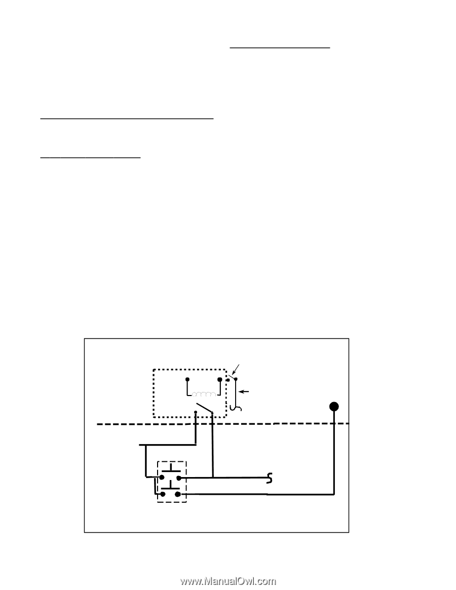
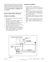
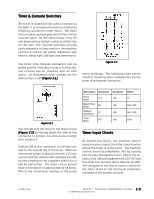
The following rules determine the maximum number of redistribution attempts that will be allowed in each spin step before the machine control skips the step and continues with the spin profile (See Section 2: Unbalance Control System). Push-To-Start Relay Operation STARTING THE WASHER 1. With the door closed, press the push-to start switch. 2. The red no. 28 wire sends a signal to the machine control to start running. 3. 120 VAC is supplied to the machine control board through black wire no. 27. 4. The machine control closes an internal switch to energize the line relay. 5. When the push-to-start button is released, power remains supplied to the machine control and the washer from gray wire no. 26 through the line relay. STOPPING THE WASHER 1. With the washer running, power is supplied to the machine control and washer from gray wire no. 26 through the line relay. 2. When the user presses the push-to-start button, a signal is sent to the machine control through red wire no. 28 telling the washer to shut down. 3. The machine control opens the internal logic switch which de-energizes the line relay. 4. When the user releases the push-to-start button, power is removed from the machine control and washer (Black wire no. 27). MACHINE CONTROL BOARD LINE R EL AY NO COM INTERNAL LOGIC SWITCH 120 VAC POWER FROM MACHINE CONTROL BOARD 120 VAC LINE (W hen door is closed) GY 26 BK 27 PUSH TO START SWITCH 120 VAC Line To Timer & Motor Control Board RD 28 Figure 1-8 16008373-01 © 1998 Maytag Corporation SECTION 1. GENERAL INFORMATION 1-12
-
 1
1 -
2
-
3
-
4
-
5
-
6
-
7
-
8
-
9
-
10
-
11
-
12
-
 13
13 -
 14
14 -
 15
15 -
 16
16 -
 17
17 -
 18
18 -
 19
19 -
 20
20 -
 21
21 -
 22
22 -
 23
23 -
24
-
25
-
26
-
27
-
28
-
29
-
30
-
31
-
32
-
33
-
34
-
35
-
36
-
37
-
38
-
39
-
40
-
41
-
42
-
43
-
44
-
45
-
46
-
47
-
48
-
49
-
50
-
51
-
52
-
53
-
54
-
55
-
56
-
57
-
58
-
59
-
60
-
61
-
62
-
63
-
64
-
65
-
66
-
67
-
68
-
69
-
70
-
71
-
72
-
73
-
74
-
75
-
76
-
77
-
78
-
79
-
80
-
81
-
82
-
83
-
84
-
85
-
86
-
87
-
88
-
89
-
90
-
91
-
92
-
93
-
94
-
95
-
96
-
97
-
98
-
99
-
100
-
101
-
102
-
103
-
104
-
105
-
106
-
107
-
108
-
109
-
110
-
111
-
112
-
113
-
114
-
115
-
116
-
117
-
118
-
119
-
120
-
121
-
122
-
123
-
124
-
125
-
126
-
127
-
128
-
129
-
130
-
131
-
132
-
133
-
134
-
135
-
136
-
137
-
138
-
139
-
140
-
141
-
142
-
143
-
144
-
145
-
146
-
147
-
148
-
149
-
150
-
151
-
152
-
153
-
154
-
155
-
156
-
157
 |
 |