Maytag MER5752BAB Installation Manual - Page 6
Torque, Specifications - installation
 |
View all Maytag MER5752BAB manuals
Add to My Manuals
Save this manual to your list of manuals |
Page 6 highlights
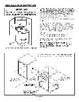
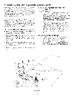
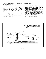
FIGURE 6 3-Wire Service Cord or Conduit Installation 1. Insure that the copper ground strap IS CONNECTED between the middle post of the main terminal connection block and the range chassis. 2. If bare copper or aluminum wiring is used, attach adapter lugs as shown in figure 6. (See Bare Wire Connection). Torque specifications are shown below. 3. The middle wire of the service cord or ground lead of 3-wire conduit MUST connect to the neutral (middle) post of the main terminal block. The other two wires of the service cord or conduit connect to the outside posts of the main terminal connection block. Polarity is unimportant. (If using bare wire, attach wire to appropriate lug as shown. Torque specifications are shown below). 4. An appropriate strain relief for service cord or conduit MUST be attached to the conduit plate. RED-- WHITE --= \ CO_JNECT LON BLOCK GROUND SII_AP _---_ (CONNECTED AT MDDLE WIRE OF SERV ICE CORD i AIN TERMINAL !3 _A_r._ E CONDU I I ¢/ PLATE BLACK-- SFTARCATIONR_ Y) _1 RELIEF _ I - RIB FIGURE 7 4-Wire Service Cord or Conduit Installation (Mobile Homes Or As Required By Codes) 1. The copper ground strap connected between the neutral (middle) post of the main terminal block and the chassis MUST be cut off as shown in figure 7. Save the green ground screw to attach the ground from the 4 wire cord. Only a 4 wire cord or conduit should be used. 2. If bare copper or aluminum wiring is used, attach adapter lugs as shown in figure 7. (See Bare Wire Connection). Torque specifications are shown below. 3. The ground wire from the service cord or conduit must connect to the range chassis using the green ground screw. 4. The white wire of the service cord or conduit must connect to the neutral (middle) post of the main terminal block. The other two wires of the service cord connect to the red and black posts of the main terminal block, respectively. (If using bare wire, attach wire to appropriate lug as shown. Torque specifications are shown below). 5. An appropriate strain relief for service cord or conduit MUST be attached to the conduit plate. ALTERNATE I NSTALLAT I ON ..... [)LITLET SHO_'N ro BE IF NOT QO]ATEO AS FLUSH TO WALl FLUSH TO WALL _ .!X_ I STAMPED CONDUET STAMPE[] CORD I FOR USE N_TH CONDUIT / REMOVE BRACKET FLIP /V &_RE ATTACH Wl TH HOLE / MARKEO "CONDUIT" DOWN FIGURE 6 NORMAL - 3 WIRE PLUG BARE WIRE CONNECTION ALTERNATE I NSTALLAT I ON OUTLET TO BE ROTATED AS x, i_ NOr ILUSH 10 WA_L Conversion From 3-Wire To 4-Wire Service (Free-Standing Models With 3-Wire Service Cord Attached), Disconnect range from power. Remove the access cover on back of range and remove the 3-wire service cord from the main terminal block. Follow instructions as outlined in figure 9 to connect the 4-wire service cord. NOTE: Cord replacement - ONLY a power supply cord rated at 240 volts minimum, 40 amperes or 50 amperes power supply cord that is marked for use with nominal 1 3/8" (34.93 mm) diameter connection opening, with closed loop terminals and marked for use with ranges shall be used. -6- Bare Wire Torque Specifications Lug attached to Terminal Block - 20 in-lb 10 - 14 8 4-6 20 in-lb 25 in-lb 35 in-tb
-
 1
1 -
 2
2 -
 3
3 -
 4
4 -
 5
5 -
 6
6 -
 7
7 -
 8
8 -
 9
9 -
 10
10 -
 11
11 -
 12
12 -
13
-
14
-
15
-
16
-
17
-
18
 |
 |
