Maytag MFI2067AE User Instructions - Page 5
Complete the Installation - parts
 |
UPC - 719881171715
View all Maytag MFI2067AE manuals
Add to My Manuals
Save this manual to your list of manuals |
Page 5 highlights
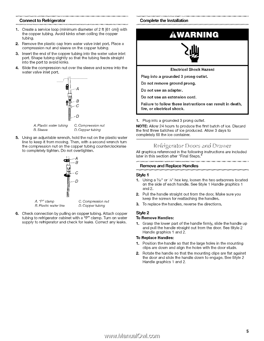
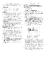
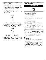
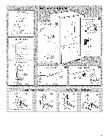
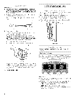
Connect to Refrigerator 1. Create a service loop (minimum diameter of 2 ft [61 cm]) with the copper tubing. Avoid kinks when coiling the copper tubing. 2. Remove the plastic cap from water valve inlet port. Place a compression nut and sleeve on the copper tubing. 3. Insert the end of the copper tubing into the water valve inlet port. Shape tubing slightly so that the tubing feeds straight into the port to avoid kinks. 4. Slide the compression nut over the sleeve and screw into the water valve inlet port. r- E ....,s o A. Plastic water tubing B. Sleeve C. Compression nut D. Copper tubing 5. Using an adjustable wrench, hold the nut on the plastic water line to keep it from moving. Then, with a second wrench turn the compression nut on the copper tubing counterclockwise to completely tighten. Do not overtighten. ql A. "P" clamp B. Plastic water line C. Compression nut D. Copper tubing 6. Check connection by pulling on copper tubing. Attach copper tubing to refrigerator cabinet with a "P" clamp. Turn on water supply to refrigerator and check for leaks. Correct any leaks. Complete the Installation Electrical Shock Hazard Plug into a grounded 3 prong outlet. Do not remove ground prong. Do not use an adapter. Do not use an extension cord. Failure to follow these instructions can result in death, fire, or electrical shock. 1. Plug into a grounded 3 prong outlet. NOTE: Allow 24 hours to produce the first batch of ice. Discard the first three batches of ice produced. Allow 3 days to completely fill the ice container. All graphics referenced in the following instructions are included later in this section after "Final Steps." Remove and Replace Handles Style 1 1. Using a 3/32"or V8" hex key, loosen the two setscrews located on the side of each handle. See Style 1 Handle graphics 1 and 2. 2. Pull the handle straight out from the door. Make sure you keep the screws for reattaching the handles. 3. To replace the handles, reverse the directions. Style 2 To Remove Handles: 1. Grasp the lower part of the handle firmly, slide the handle up and pull the handle straight out from the door. See Style 2 Handle graphics 1 and 2. To Replace Handles: 1. Position the handle so that the large holes in the mounting clips are down and align the holes with the door studs. 2. Rotate the handle so that the mounting clips are flat against the door and slide the handle down to engage. See Style 2 Handle graphics 1 and 2.
-
 1
1 -
 2
2 -
 3
3 -
 4
4 -
 5
5 -
 6
6 -
 7
7 -
 8
8 -
 9
9 -
 10
10 -
 11
11 -
12
-
13
-
14
-
15
-
16
-
17
-
18
-
19
-
20
-
21
-
22
-
23
-
24
-
25
-
26
-
27
-
28
-
29
-
30
-
31
-
32
-
33
-
34
-
35
-
36
-
37
-
38
-
39
-
40
 |
 |